
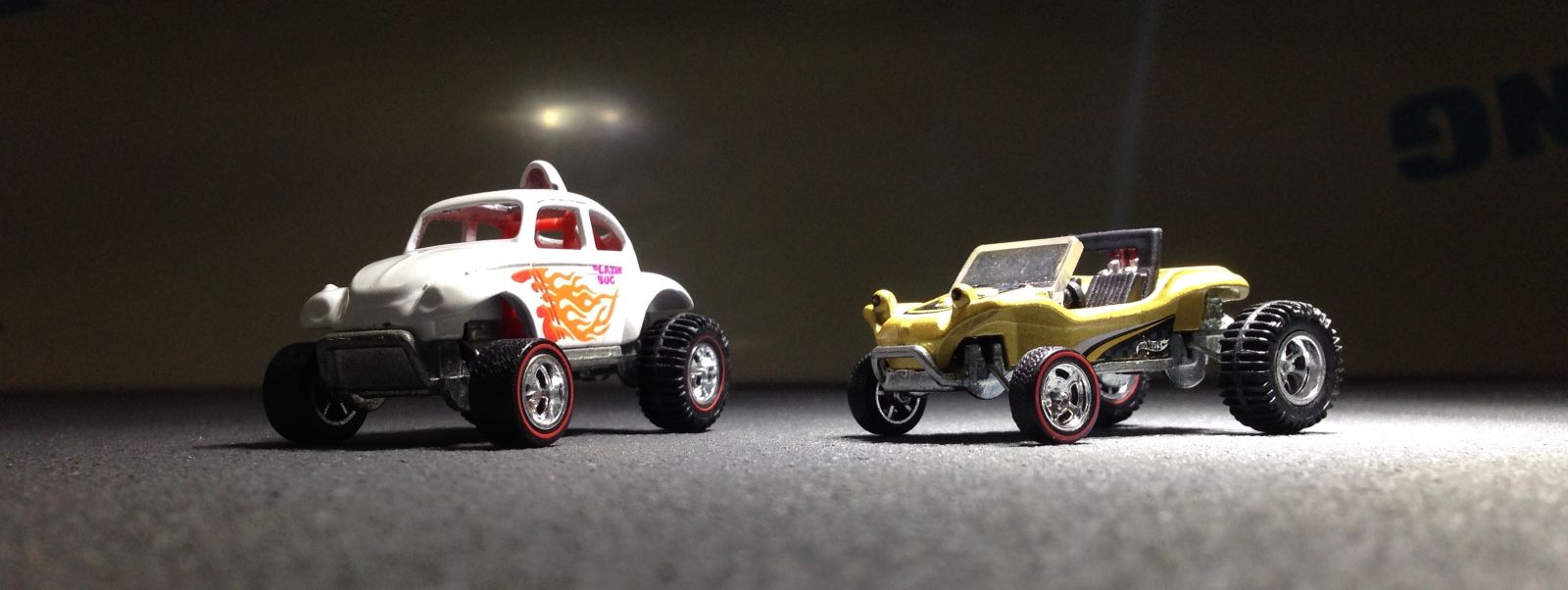
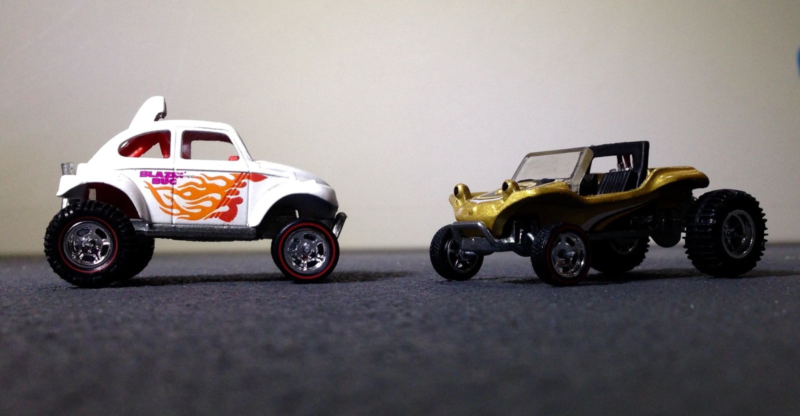
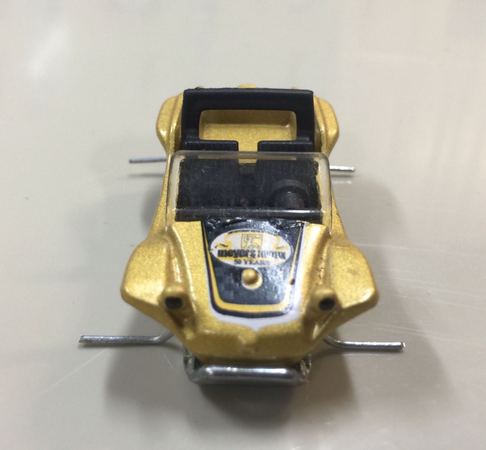
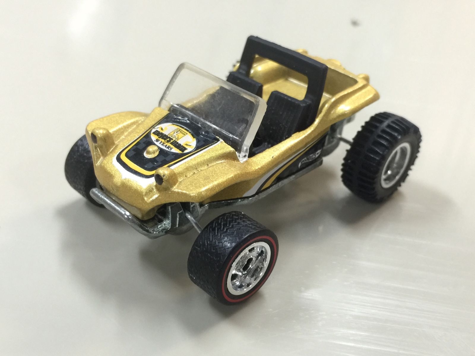
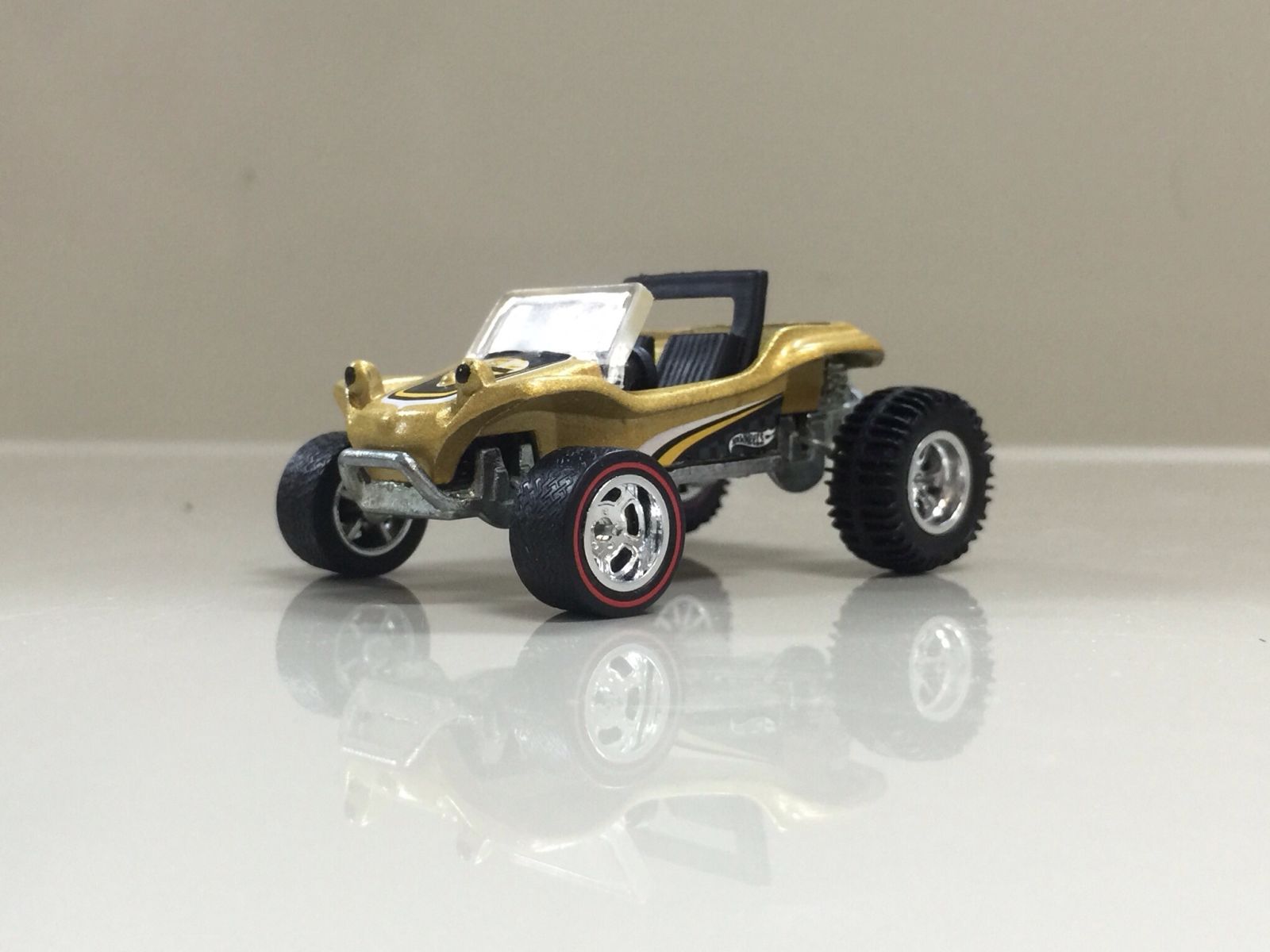
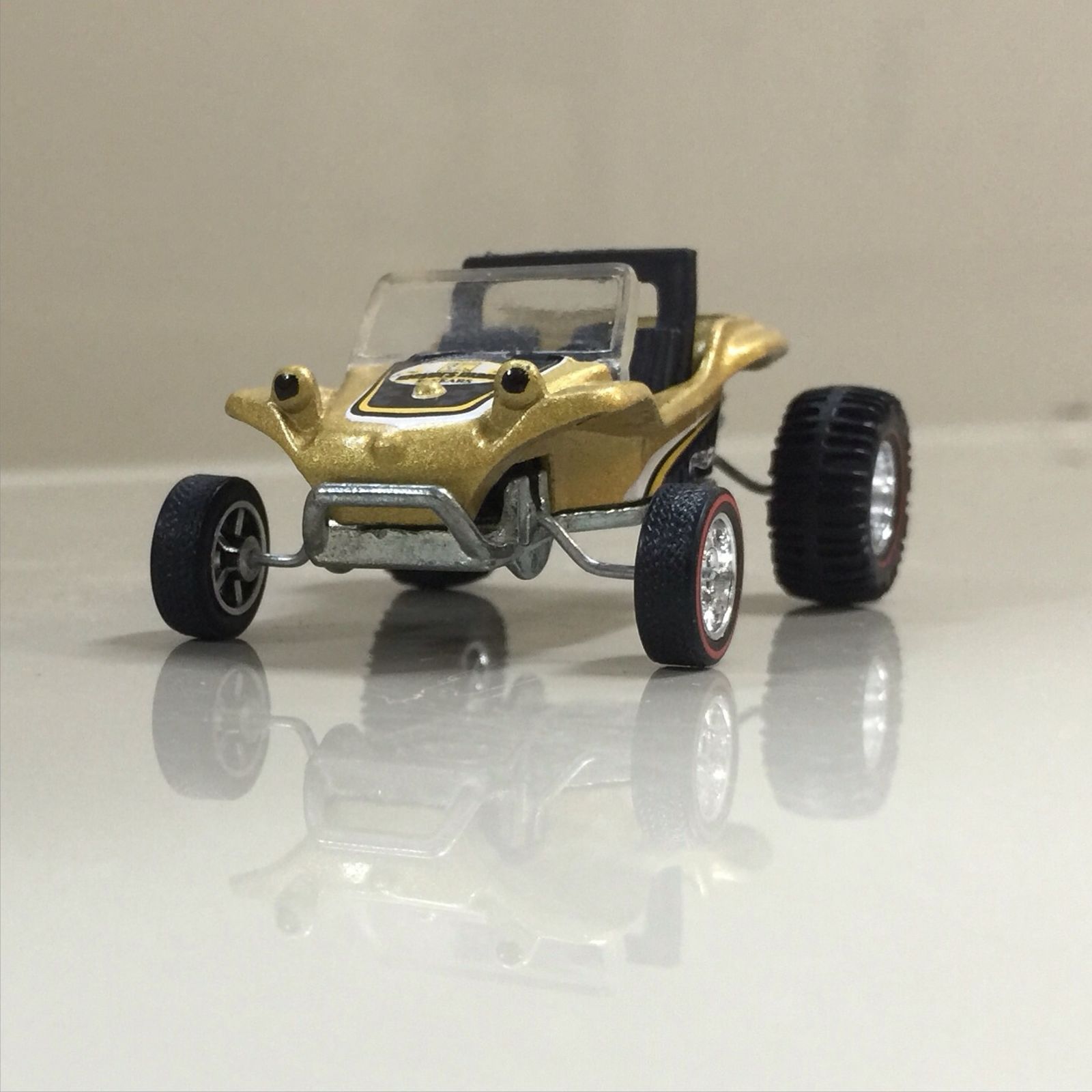
So I finally got time for a full post on how I lifted the Meyers Manx and BAJA Bug. First a few pictures of the pair together then on to the build.
Ok, I’ve skipped the drilling and tapping stage but if you don’t know how it’s done I’ve made this short clip on how I do it right here: http://liveandletdiecast.kinja.com/ever-wondered-…
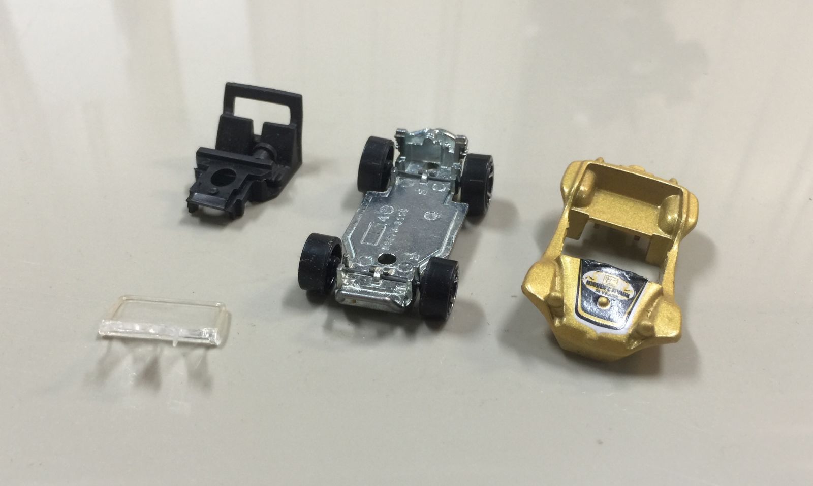
Broken down to its parts.
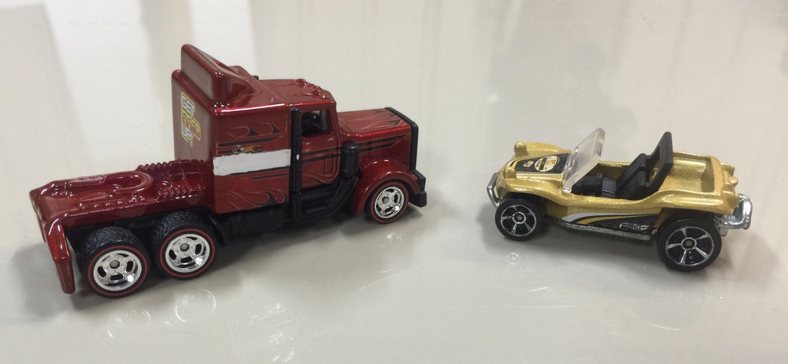
The donor and recipient. These trucks are great value for wheels swaps. Two trucks yields three pairs of wheel sets plus the fronts are hard to get skinny versions.
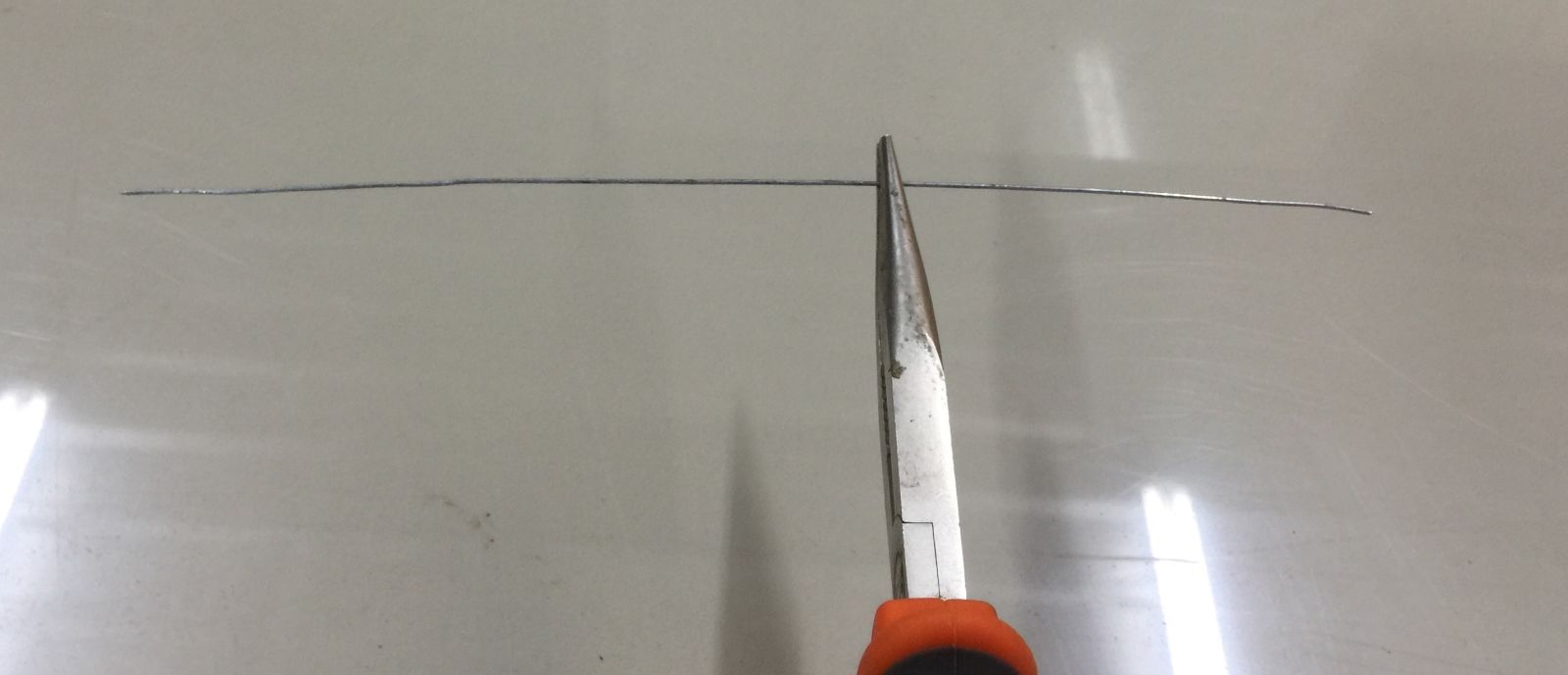
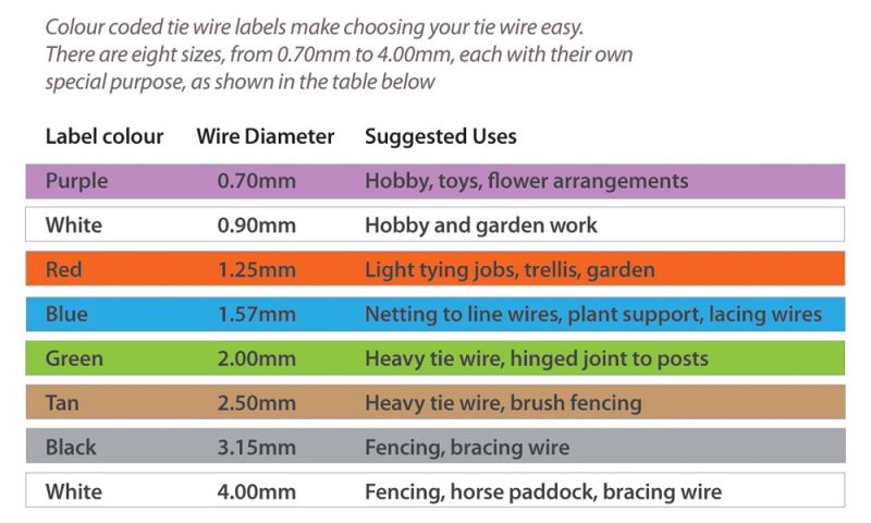
Time to start. I used some soft wire I have around for fence work. It’s readily available in hardware and garden stores. It’s dia is .9mm or around .036in or 19 gauge.
Note: Sample shot not of the right dia.
Images and info from here: http://www.whiteswires.com.au/SearchResults/…
I started with the rear axle as it has the larger wheels, once I have those in the right place I can work out where the front will end up.
I cut a piece of wire around 100mm (4”) long and bent it into a ‘U’ shape using the pointy nose pliers.
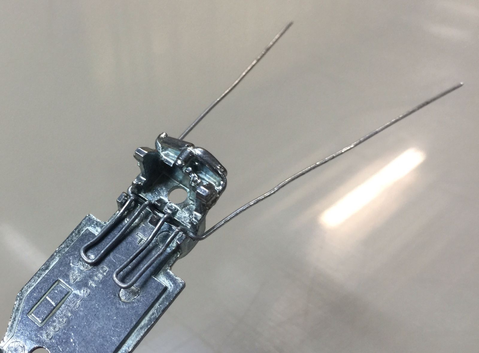
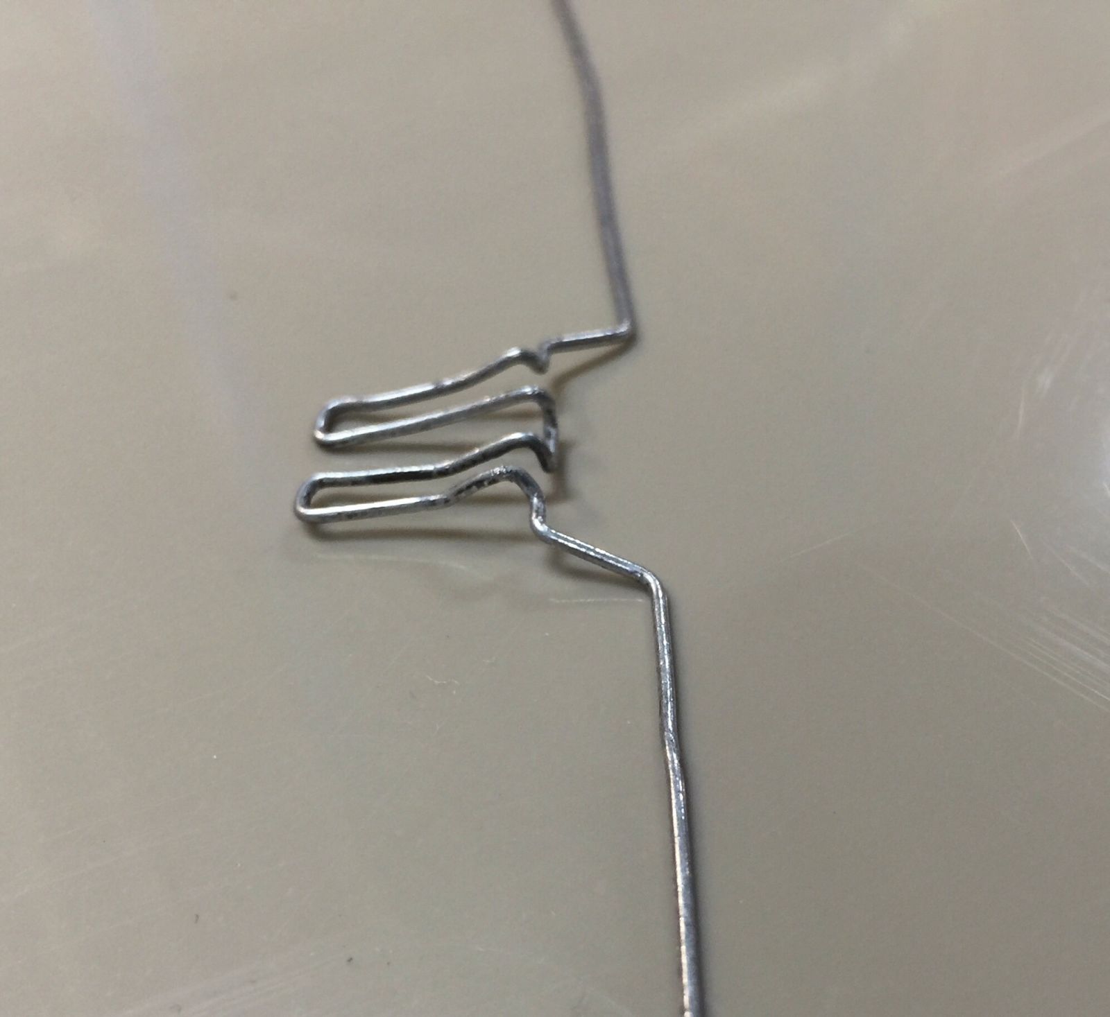
I needed a way to stop the axle from pivoting once the weight of the cast is on the wheels. To do this I bent a couple of legs to run forward of the stock axle mounts and then back again, once the cast is back together they become sandwiched between the base and interior part. This actually holds the axle in place very solidly once screwed back together and no mods were needed to the interior.
The two legs are done. I also had to add the small bend at the base of the ’U’ to allow that to sit it the center of the stock axle area. May have been overkill but the finished axle is very sturdy.
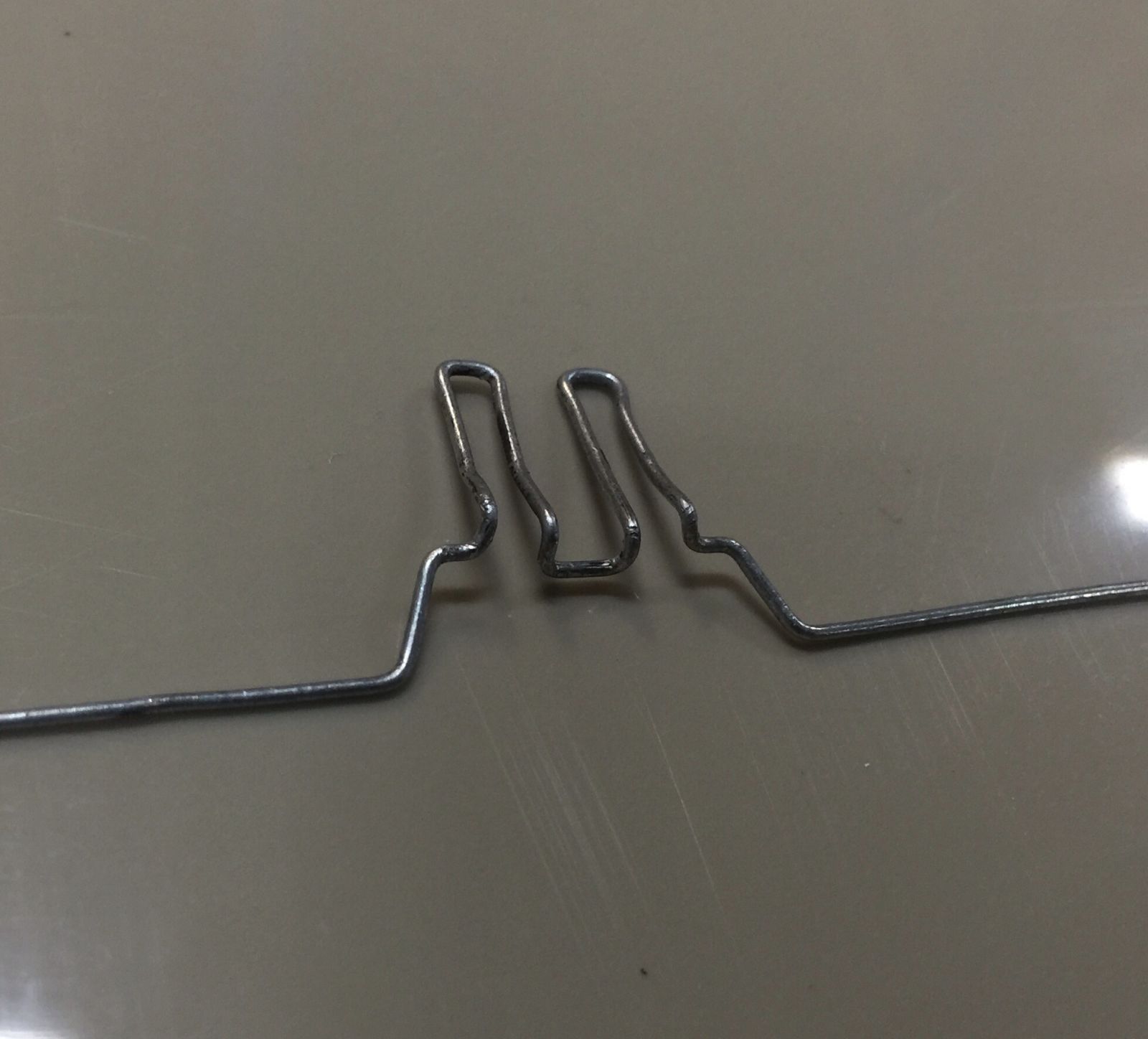
Next two bends are so the wire can come out of the base where the stock axle would normally go.
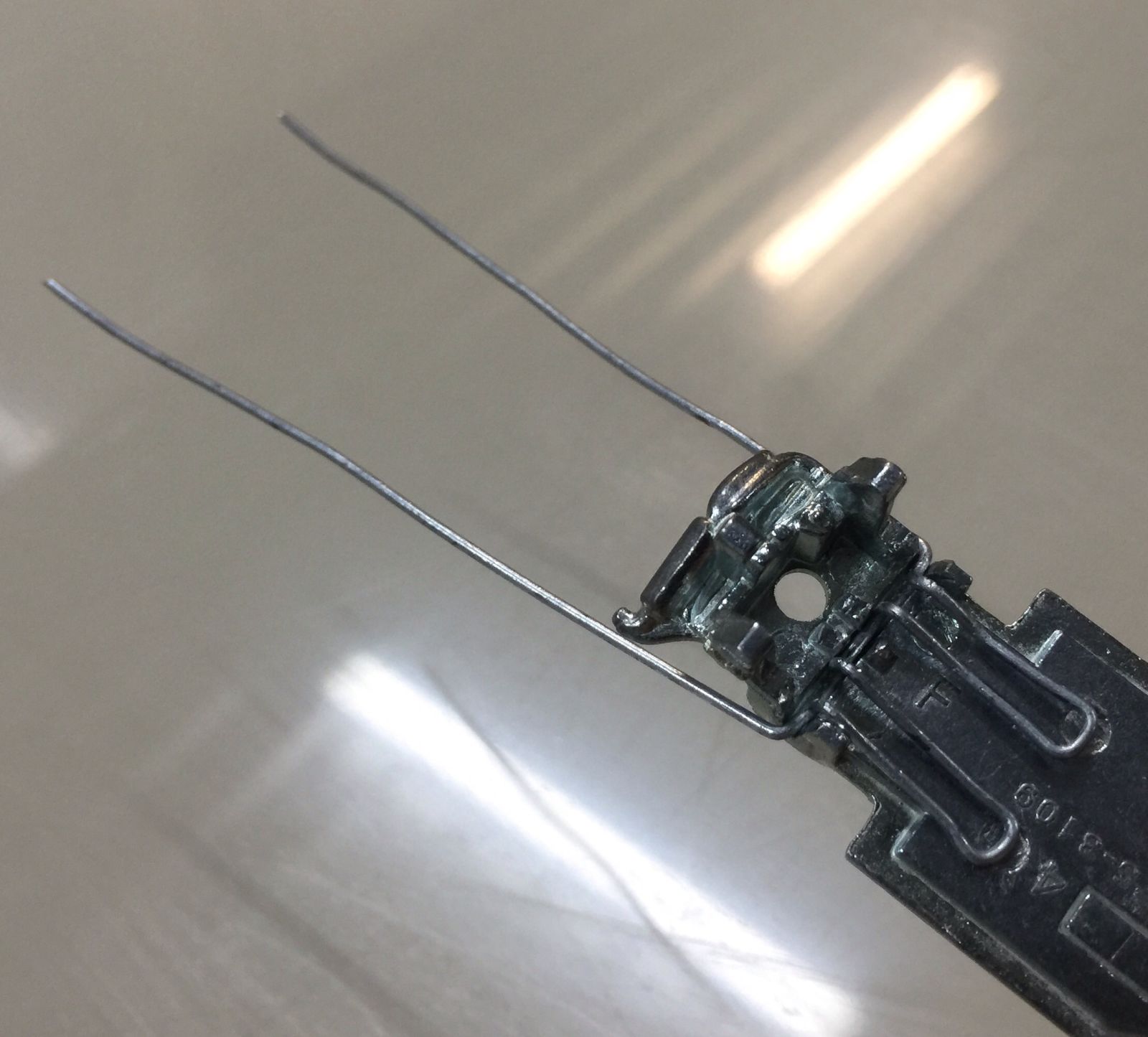
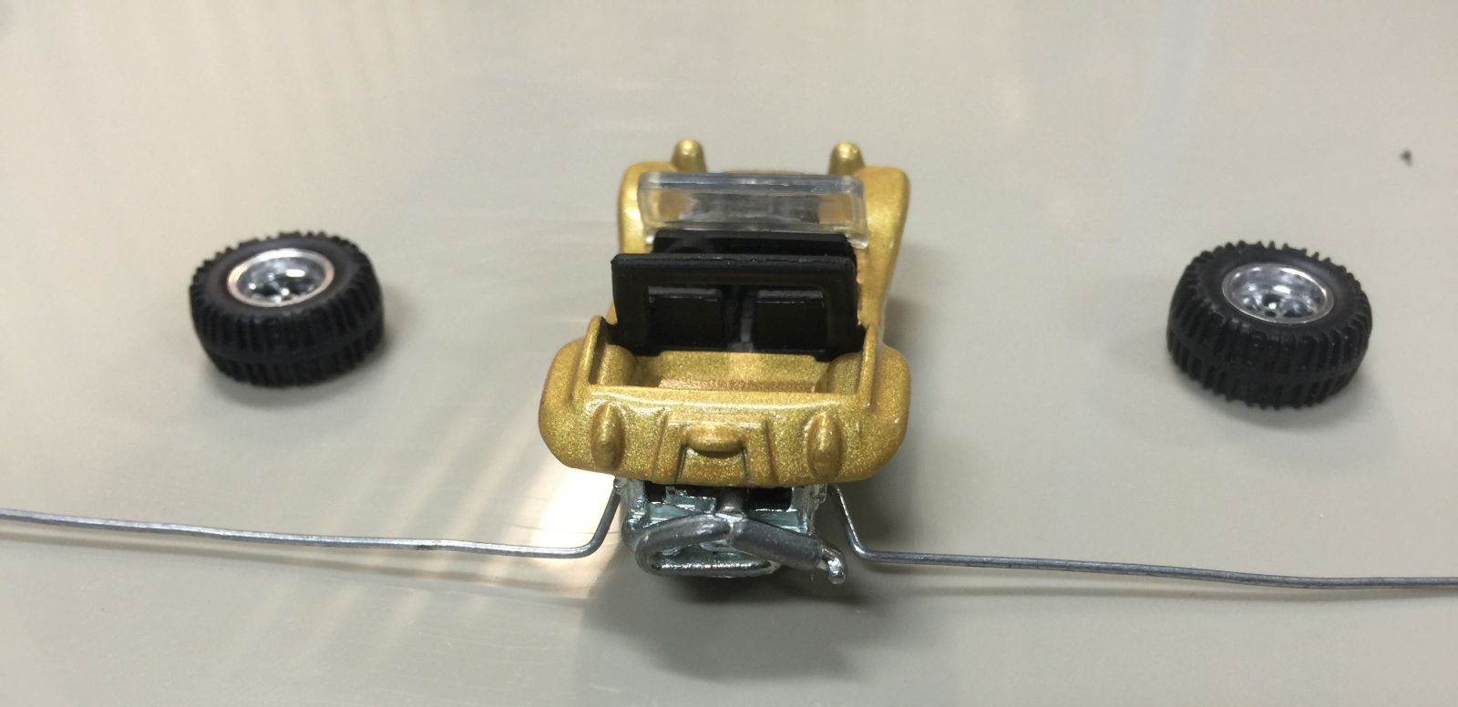
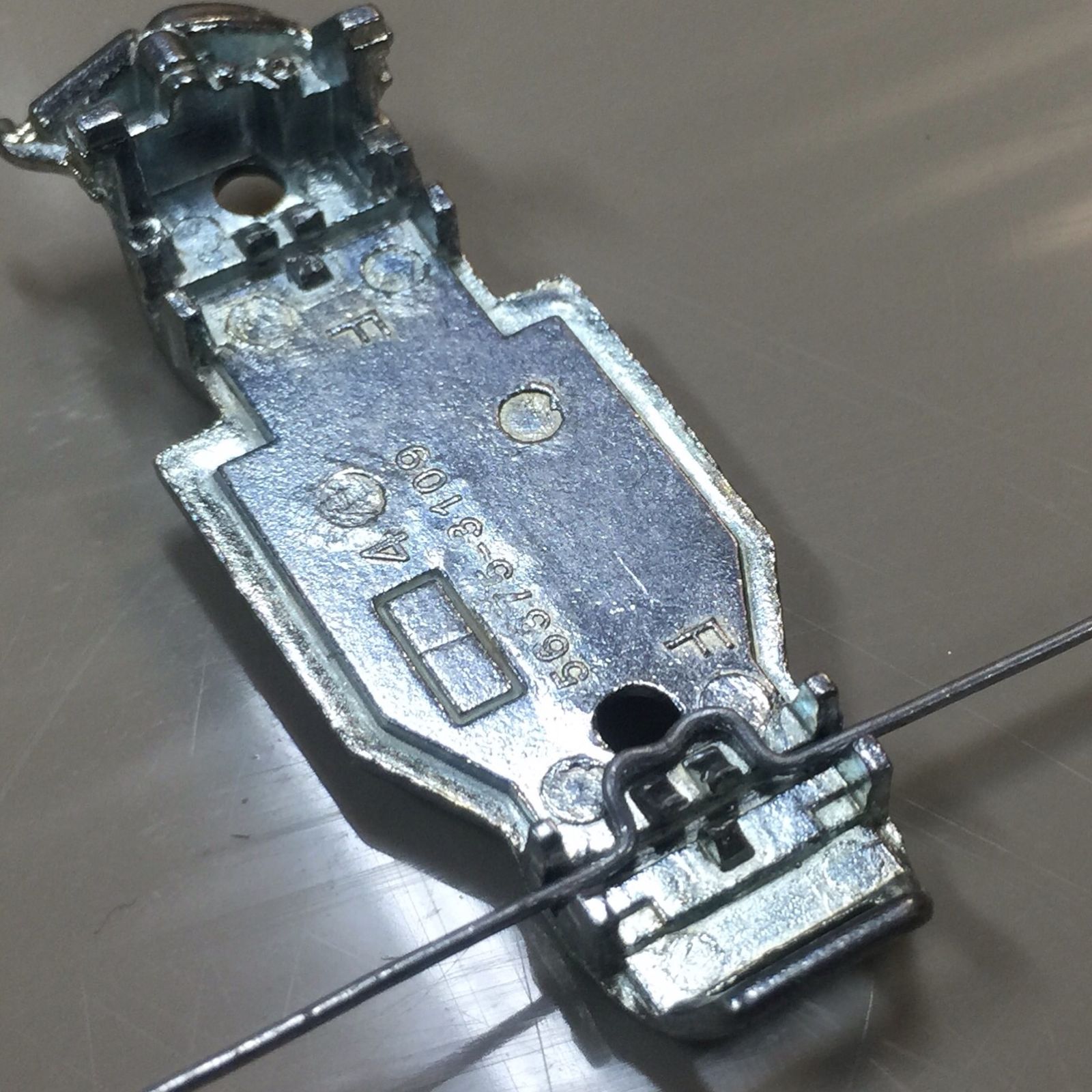
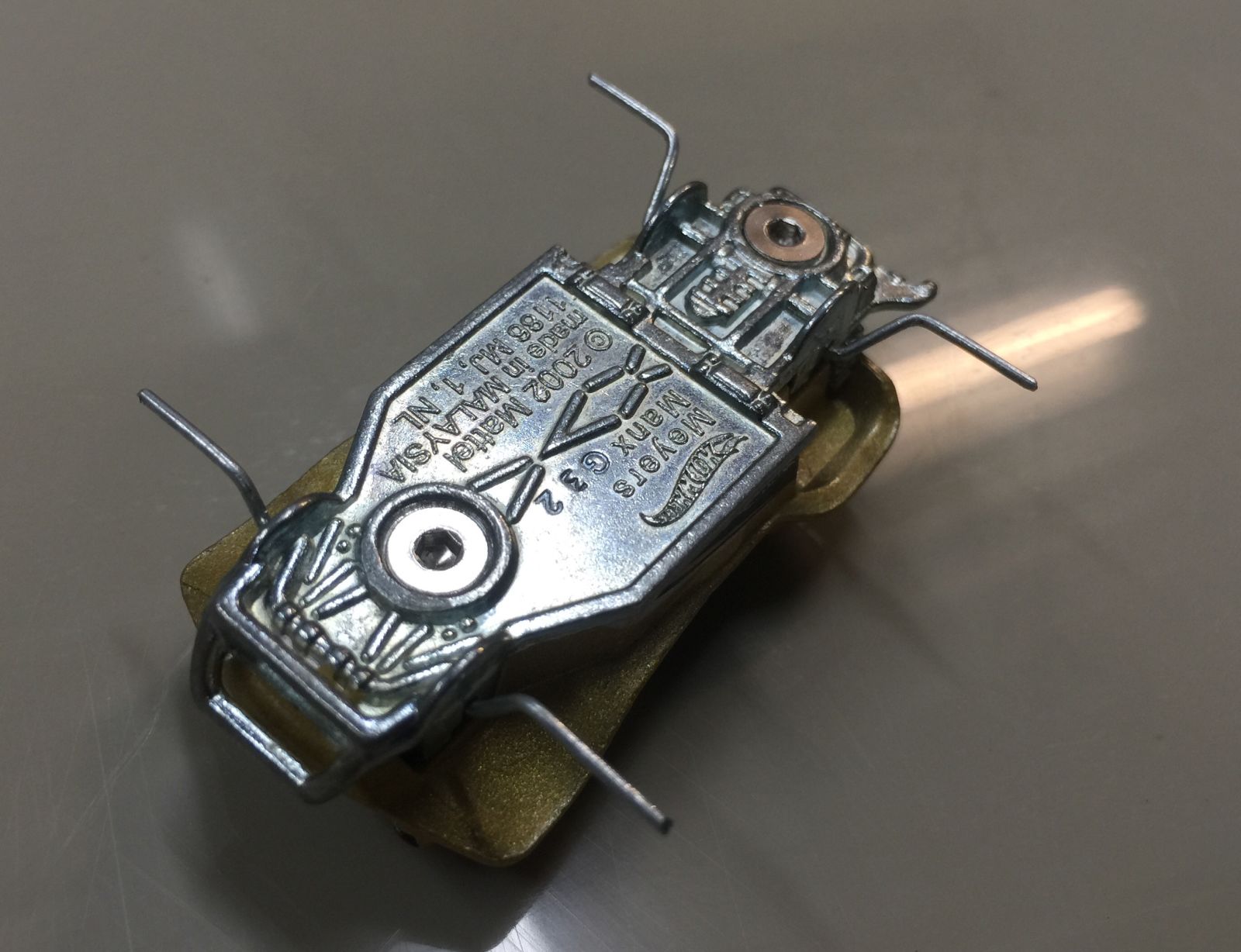
Here’s a few shots showing it in position on the base. I’ve now bent the wire while in position, so not using the pliers but just pushing it around the cast with my thumb as close to the bend as possible.
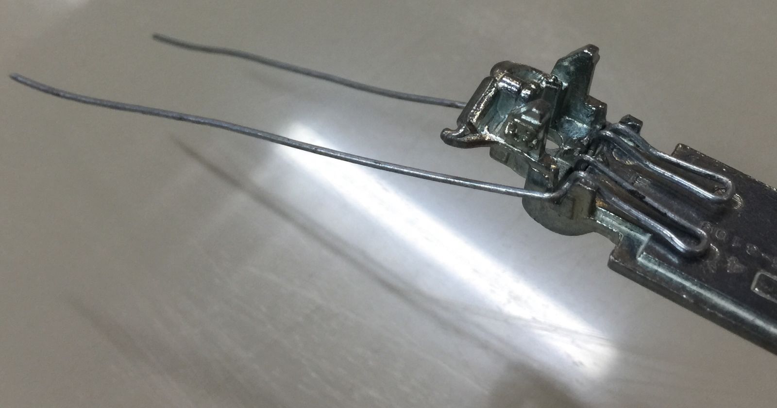
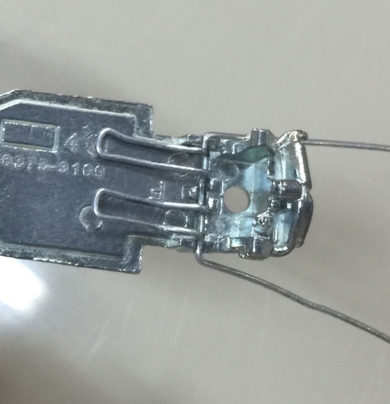
Screwed back together for a test fit to make sure the base and body fit with the wire, passed this test.
So next I bent the wire at what I thought looked like the right place to mount the wheels. I held the wheels where I wanted them to end up and used that as a guide for the bend position. This wire is able to be bent and straightened a few times without snapping so if it was wrong I was able to adjust it without starting over. I took advantage of that fact a number of times during this process.
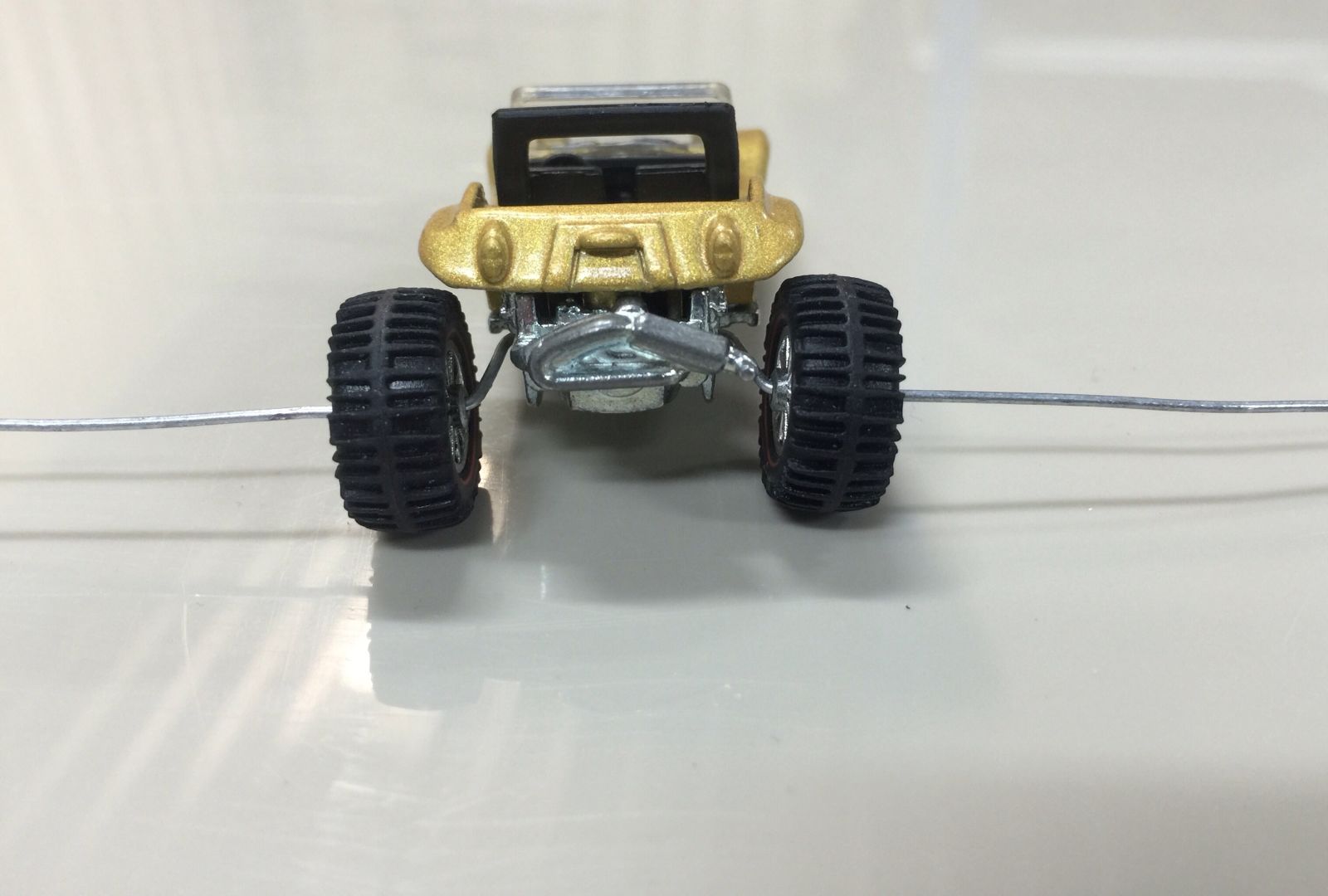
Test fit of the wheels, this is where I adjust and check the alignment and camber. ;)
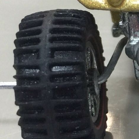
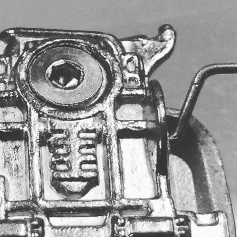
Extreme close up.
Once I was happy with the look I could trim the axles to length. To hold the wheels on I make a slight bend on the protruding bit of wire being careful to leave enough space for the wheel to spin freely. After that is correct I trim the excess to as short as possible with side cutters.
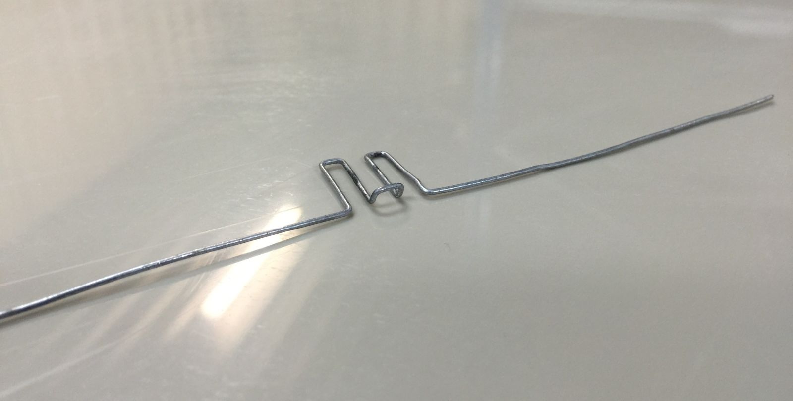
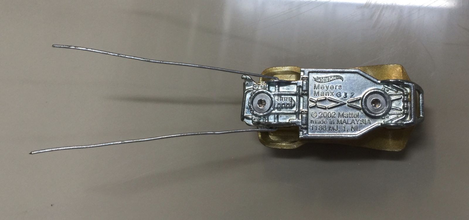
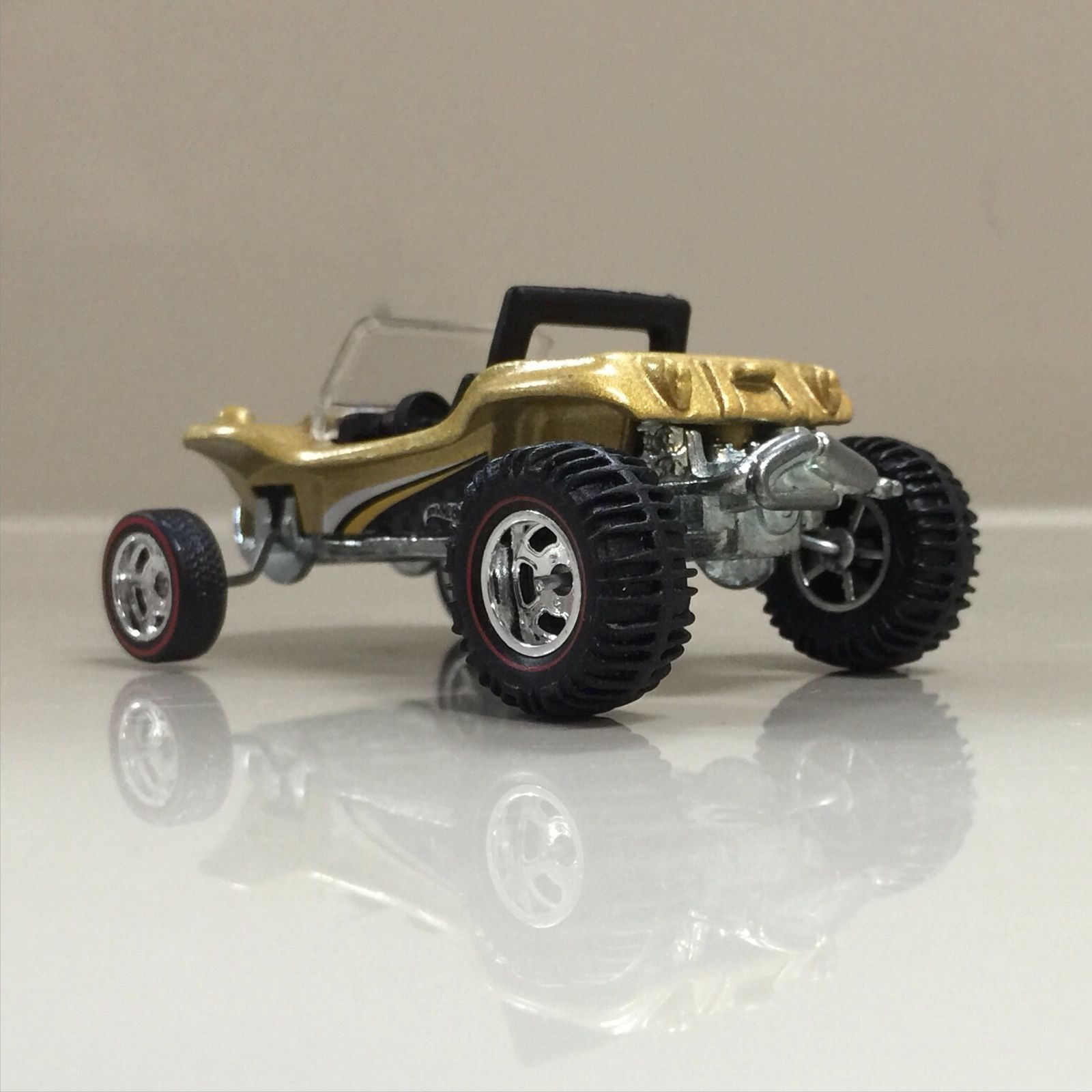
This is how the final shape turned out. Looking at it done now it looks a bit complicated but taking it one step at a time it’s not hard to do.
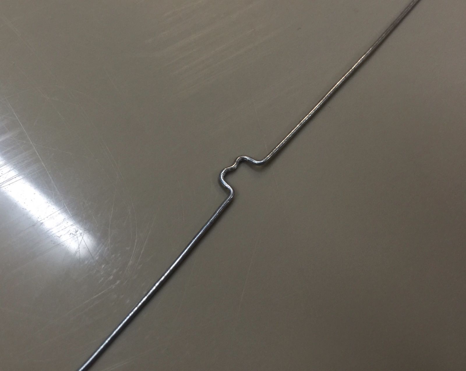
Now for the front. Thankfully it’s a much simpler part.
I had to put the little kink in the center to clear the screw but could have made it a little longer or shorter to avoid the hole altogether. This was enough the trap it between the post and base, again to stop it from pivoting once screwed together. So much easier than the rear!
Looking back I could probably have made the rear axle in a similar fashion to the front, you live and learn. :)
I did skip a couple of bends here but all the other bends were outside the cast so are visible anyway.
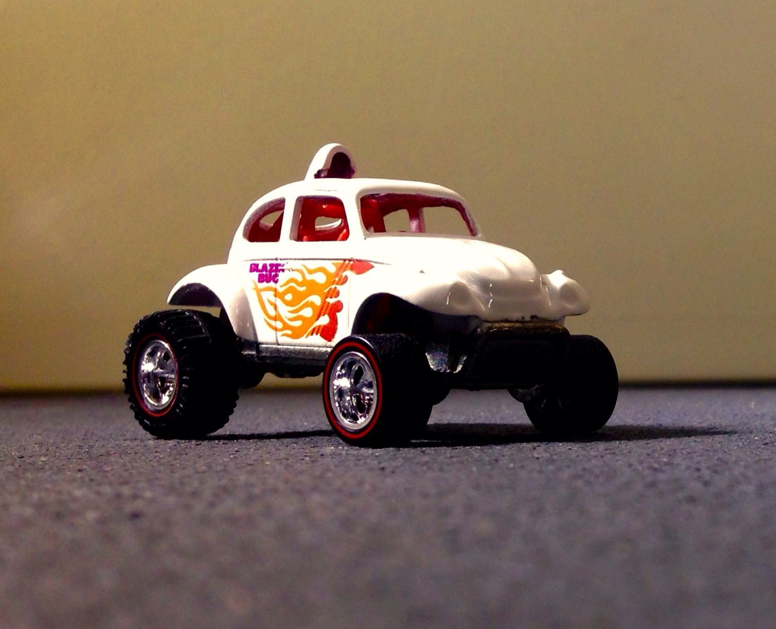
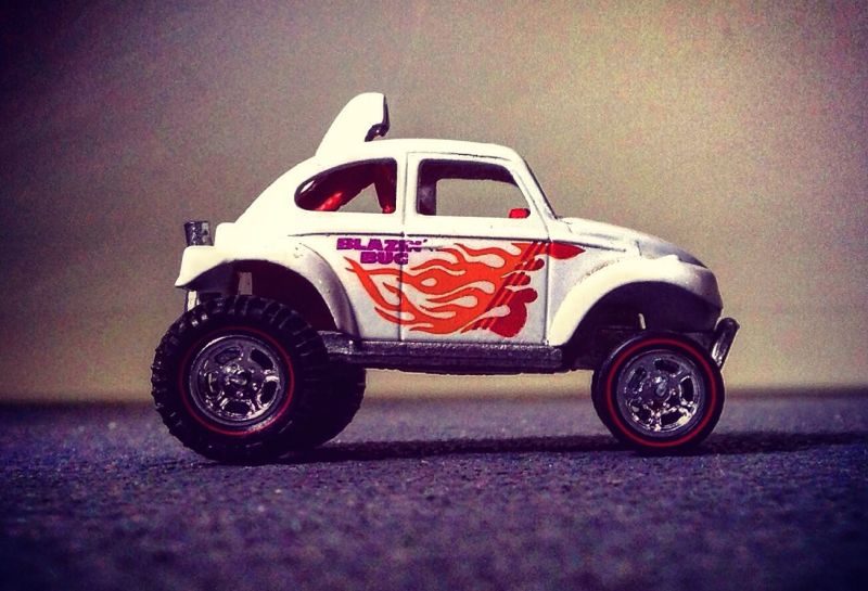
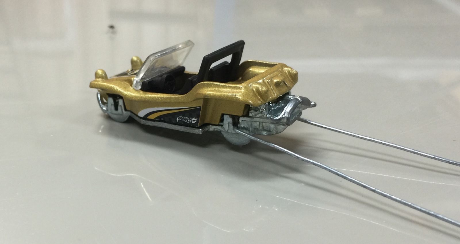
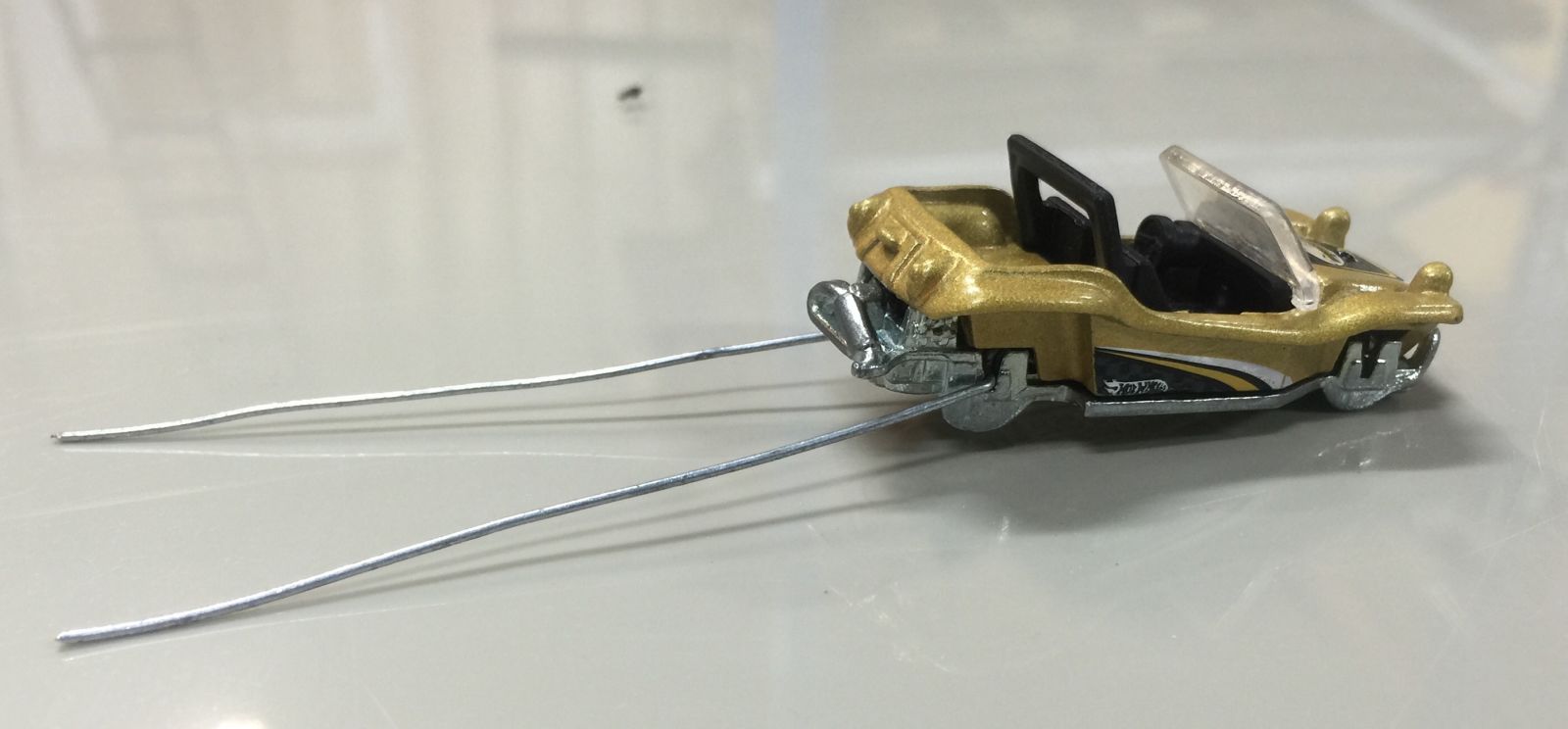
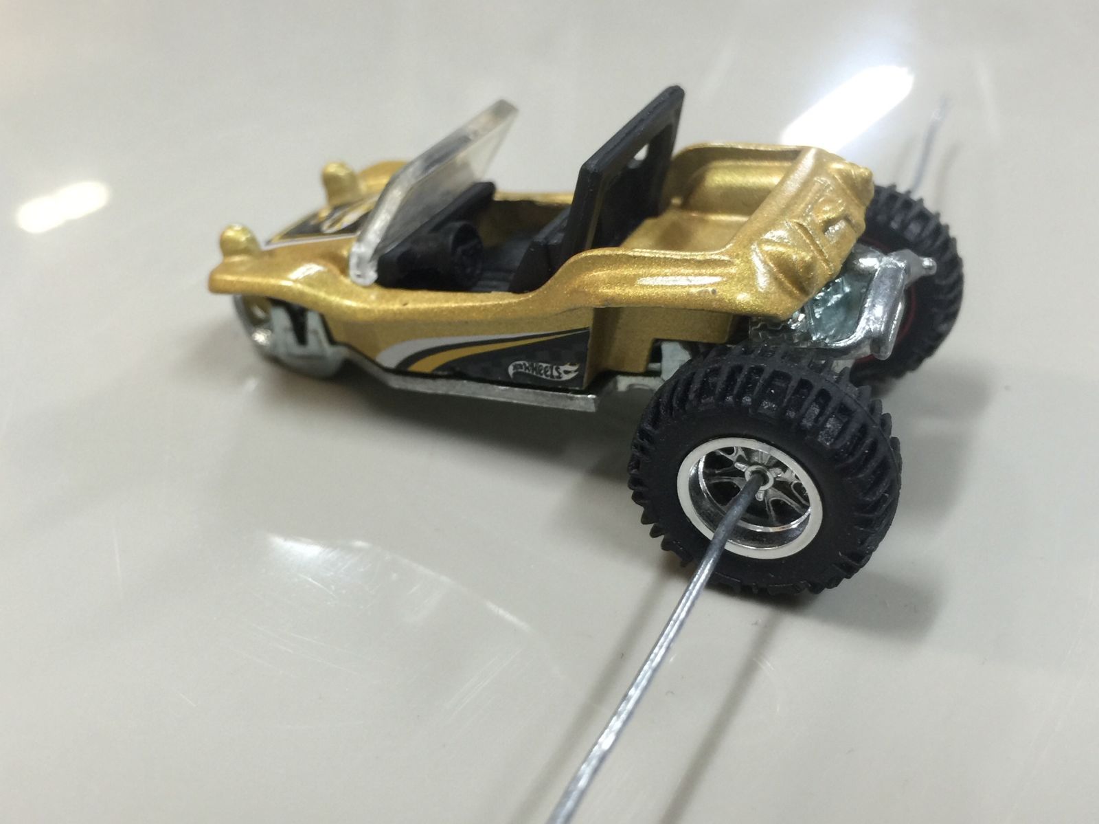
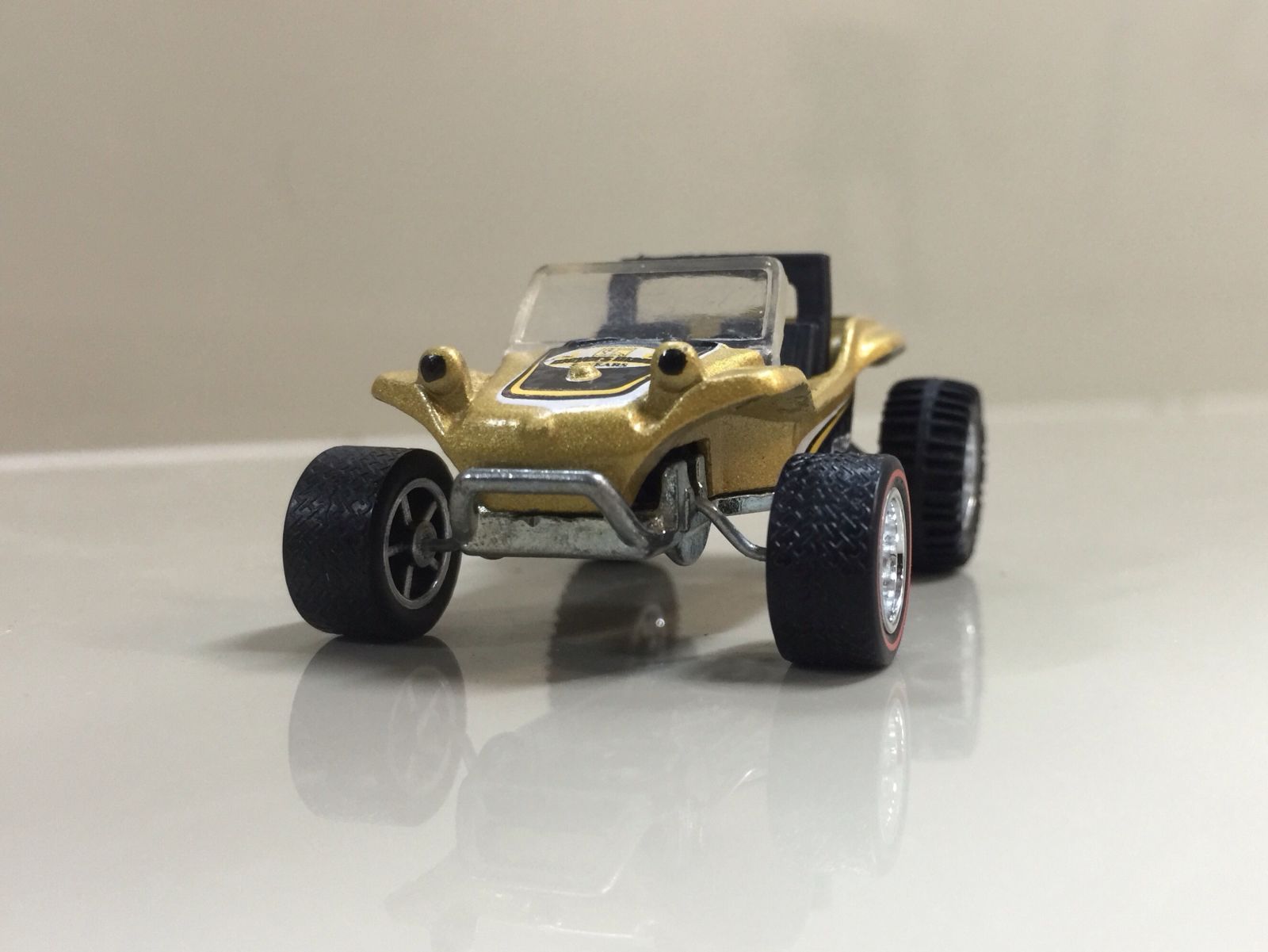
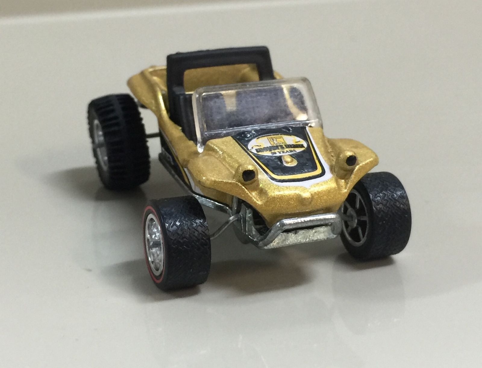
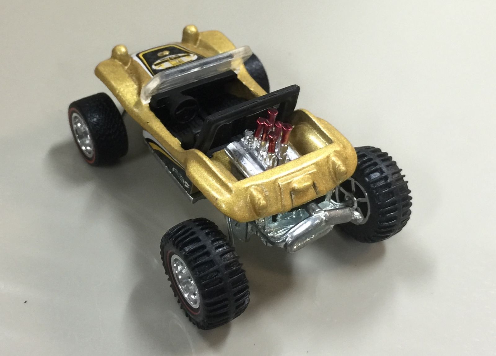
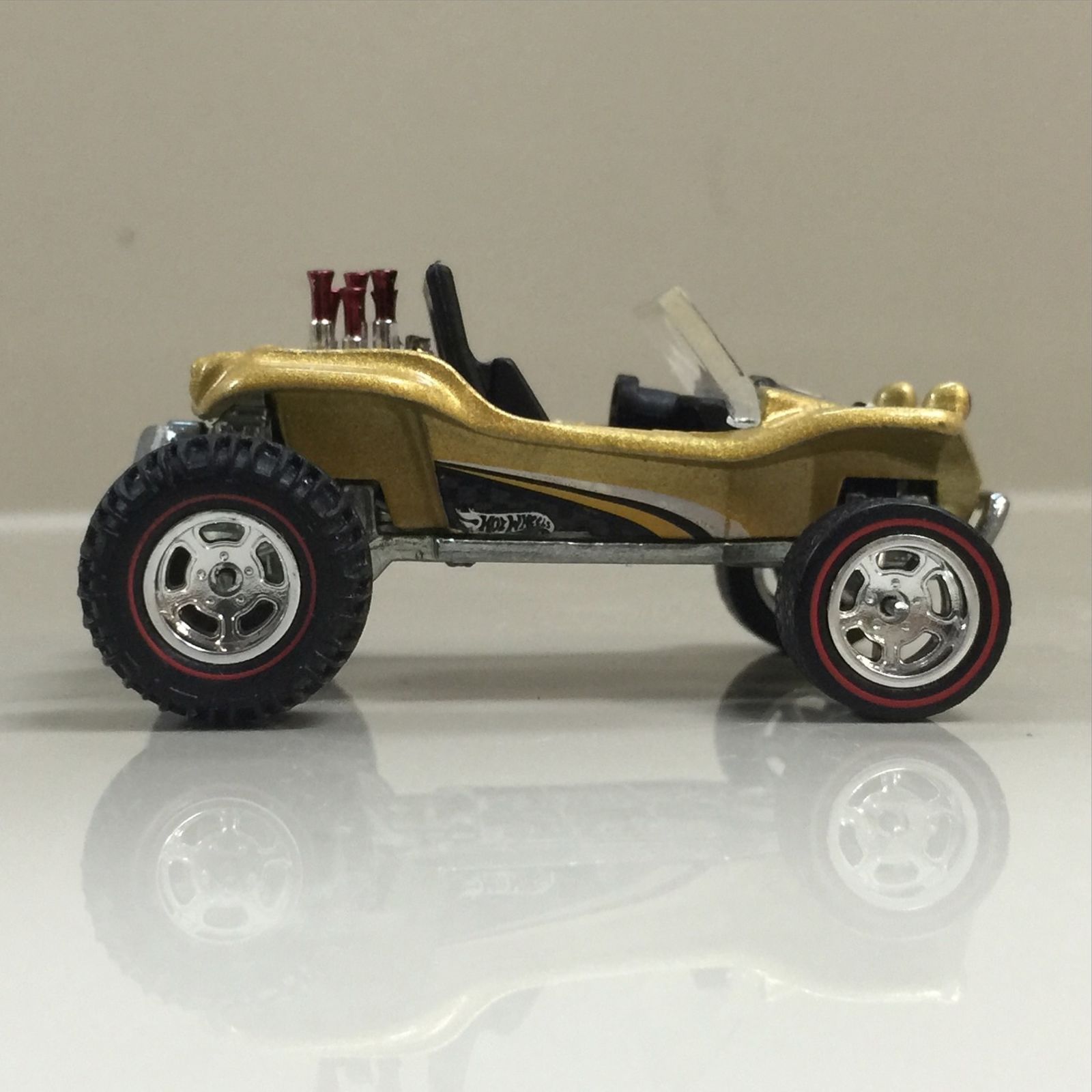
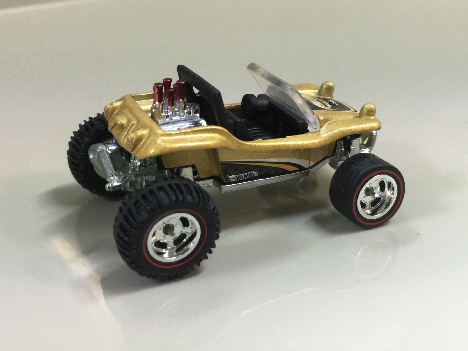
So that’s done, time for some wheels. I’ll leave you with a photo dump of the Manx, it’s my favourite of the pair. Eventually I’ll add more details to the lights and so on. Maybe even some drive shafts, (Jobjoris might be happy then :P)
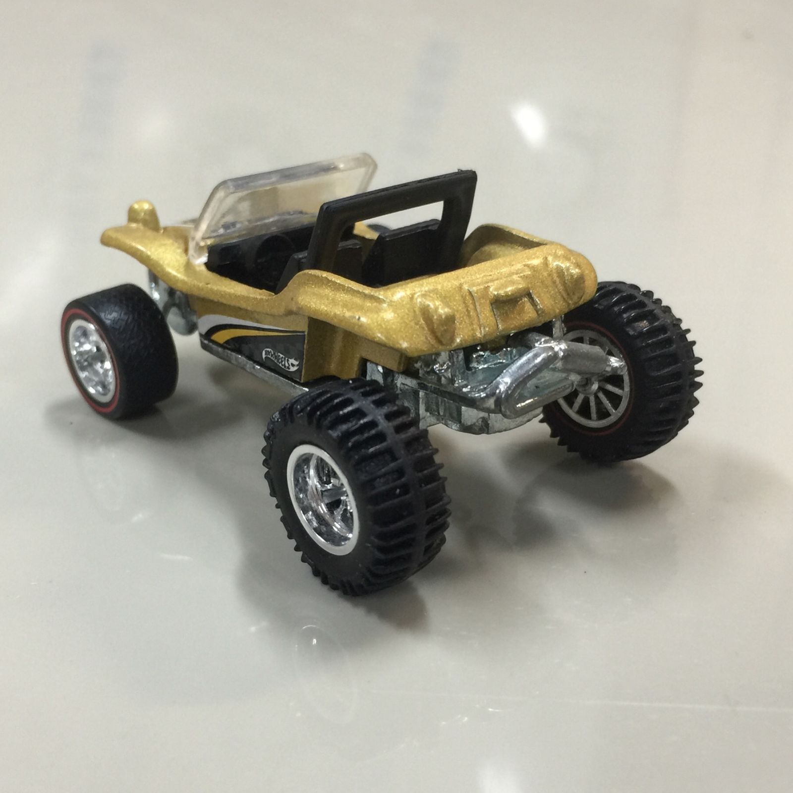
Thanks for looking.