
Gas engines, diesel, hybrid, electric, lasers…it doesn’t much matter what engine you have they all need to get the power to the wheels and if you can’t have one in each wheel, you’ll need a way to split the power between them wheels and do it while still allowing the car to turn; To this end the differential was created and it was good. Differentials are good, but they can be confusing in their operation but I aim to fix that today, at least to the extend I can.
(NOTE: Originally publish July 2015, being republished now that its been substantially re-written to suck less.)
Terms
Trg – Torque at the Ring Gear. This is the amount of torque you end up with after the engine produces the force and is multiplied by the transmission and differential.
Example: 100 lbs-ft engine with a 3:1 first gear ratio and a 4:1 ring gear ratio is 1200 lbs-ft Trg. (100*3*4 = 1200).
µ (Mu) – Greek letter for the coefficient of friction. The larger the number the harder is it for the object to overcome the resistance of friction– stickier, tire to ground.
N - Normal Force (“N”). The force exerted up from an object perpendicular to its plane. In the case of our discussion, the normal is the force equivalent to gravity times mass pressing down on the road, or weight.
F – Tractive Force (“F”). Tractive force is the amount of force that can be applied to the ground to overcome inertia and produce acceleration. The formula is F=µN.
Example: 1000 lbs [Normal force] x 1 [µ] = 1000 lbs force (1000 lbs-ft torque at a 12 inch lever arm) can be applied to road through the tire before the bond of friction is broken and traction is lost. Tractive force works on Newton’s 3rd law (every action has an equal and opposite reaction). The amount of tractive force you can apply is equal to the amount of resistance the surface you are on is pushing back against your tires.
Example: an engine rated at 1000 lbs-ft max torque can only produce that if 1000 lbs-ft of torque resistance is applied. If only 10 lbs-ft of resistance is applied then it is only producing 10 lbs-ft (ignoring friction losses in the machine)
TBR – Torque Bias Ratio. The amount torque [force] that can be sent across from one side of the differential to the other, expressed as a ratio, usually to 1. Example 4:1 TBR means 4 times the torque of one side of the differential can be biased to the other.
Speed Bias – To differentiate from torque bias, this is what allows wheels to drive at different speeds to allow for cornering or to reduce front/rear axle bind but isn’t related to torque being applied to the wheel.
Example: one tire spinning on ice and the other stopped represents a speed bias but it does not mean that no torque is going to the stopped wheel.
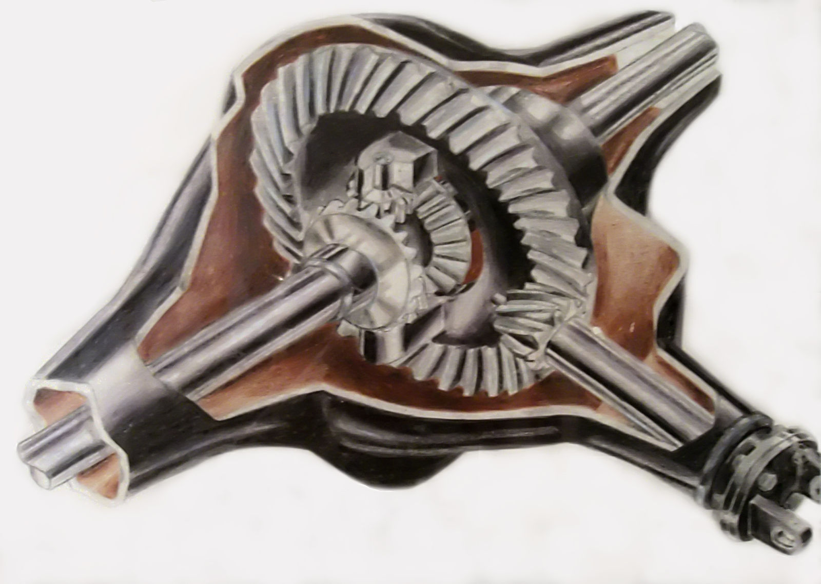
OPEN DIFFERENTIAL
Which leads me nicely into my first point regarding differentials: All differentials have a TBR of at least 1:1. The practical application of this is that open differentials, the cheapest and most common type, always split the force from the Trg half to one wheel and half to the other…50/50. Yes, always.
I hear you say. To which I would say in my best Adam Savage: Myth Busted!
The amount of torque an open differential sends down each shaft is ALWAYS 50/50. This is due to the spider gears being pushed with equal force by the carrier because they are mechanically meshed. An open differential was designed to solve the speed differentiation issue, but its design isn’t capable of biasing torque across the differential and what that means is that what one wheel gets so does the other…always.
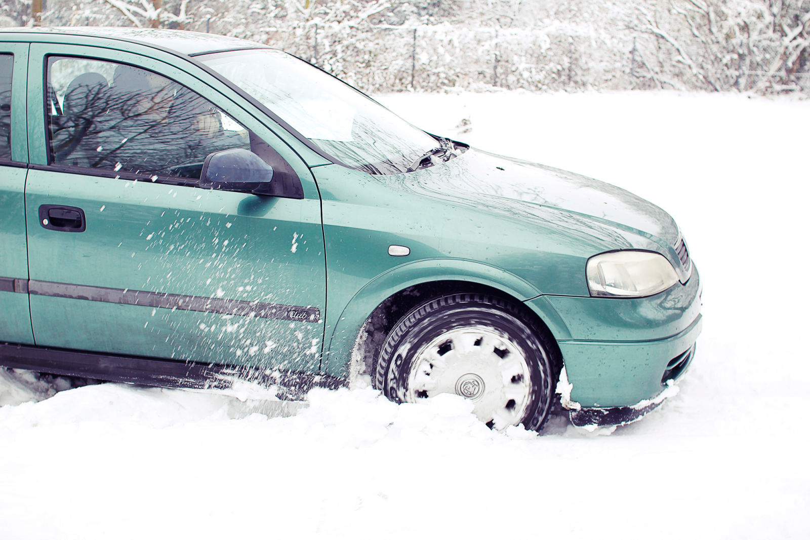
So what is going on when I’m stuck in snow and ice with one wheel spinning going nowhere? We need to look at the tractive force.
- 4000 lbs car
- 1000 lbs per wheel (assuming balanced car)
- µ snow = .3
- Tractive Force = 300 lbs (1000 x .3)
That tractive force is the max amount the tire on the snow can apply to the ground before losing traction. Because an open differential has a TBR of 1:1 it means that the amount of torque that can be applied at one end is the max of torque that can be applied at the other, thus 600 lbs of force (300 x 2) is all the car can put down even if the other side has much higher traction potential. Since this is an insufficient amount of force to overcome inertia what happens is that the wheel with less Tractive Force slips and the car goes nowhere.
In a perfect situation (equal available traction) there is no disadvantage to an open differential since it will send 100% available Trg to the tires and then the road if the road has sufficient resistance to meet its demand.
So let’s talk about other options for differentials that solve the problem, they boil down…more or less…into 3 different categories.
- Locking Differential
- Limited Slip Differential
- Electronic External Differential/Traction control
The first 2 work on the principle of increasing the TBR, the 3rd is a little different but we’ll get to that later.
LOCKING DIFFERENTIAL
As I just mentioned this type of differential works by increasing the TBR, in an extreme way.
The idea of a locking differential is to remove the differential and bias from the equation altogether. Forcing the axles halves to act as one does two thing;
- Increases the TBR to 100:0
- Removes the ability to speed bias
There are several ways to lock a differential but they all have the same effect, what one side does, so does the other, this is obviously bad if you need the wheels to travel at different speeds while cornering and this shortcoming is exactly why the differential was invented, but that shortcoming aside it has tremendous implications on traction.
Using the same numbers as before
- 4000 lbs car
- 1000 lbs per wheel (assuming balanced car)
- µ snow = .3
- Tractive Force = 300 lbs (1000 x .3)
- 300 + infinite (max traction of good grip wheel = 1000 here) = 1300 lbs
It looks much the same as the open differential example but here is the difference; the wheel in the snow no longer calls the shots for where the Trg goes.
Adding the totals up we get 1300 lbs force that can be applied, more than 2x the total tractive force we could apply with an open diff and sufficient to overcome inertia. In the case of a locking differential we biased torque across the axle to where it can be better applied; In this case at the TBR is ~3.3:1. What’s great about a locking differential is that have the potential (minus losses) to deliver an infinite TBR. Example: if one wheel is in the air where the tractive force of that wheel is 0, the wheel on the ground can still apply 1000 lbs resulting in a ratio of 1000:0
The downside to the locking differential is that it’s no better than a solid axle without a differential for speed bias when engaged, resulting in bind, increased turning circles potential damage from binding or biasing large amounts of torque and generally being dangerous on the road.
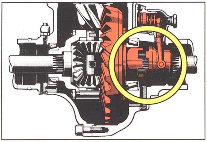
LIMITED SLIP DIFFERENTIAL
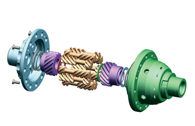
A limited slip system is EXACTLY what it sounds like: A device that allows slip, but in limited degrees, or looked at another way, limited locking. Limited slip systems are anything with a TBR greater than 1:1 up to and including a fully locked state.
There are lots of great LSD methods and types but ignoring their mechanical differences they all function on the same principles of increasing the TBR.
Back to the numbers lets assume a LSD with a TBR of 2:1
- 4000 lbs car
- 1000 lbs per wheel (assuming balanced car)
- µ snow = .3
- Tractive Force = 300 lbs (1000 x .3)
- 300 x TBR 2 = 600 lbs
- 600 + 300 = 900 lbs
Since the LSD can bias 2x the max torque for the low traction wheel to the high traction wheel we end up with 600 lbs force max on the high traction side, less than the 1000 lbs available to the high traction wheel but combined with the low traction wheel a total of 900 lbs is available, enough to overcome inertia and you move.
Change the TBR to 4:1 and you can see how powerful an LSD can be as a traction aid.
300 * 4 = 1200 + 300 = 1500 lbs potential max torque, however the high traction wheel would lose traction at 1000 lbs netting a possible 1300 lbs, the same as the locked diff. The difference is that an LSD is not infinitely biasing like a locked diff, so in the example of the wheel in the air 0 lbs force x 2:1, 4:1, 50:1, etc. is still 0.
TBR can be best described as the middle ground between no torque bias and infinite torque bias, or a locked state.
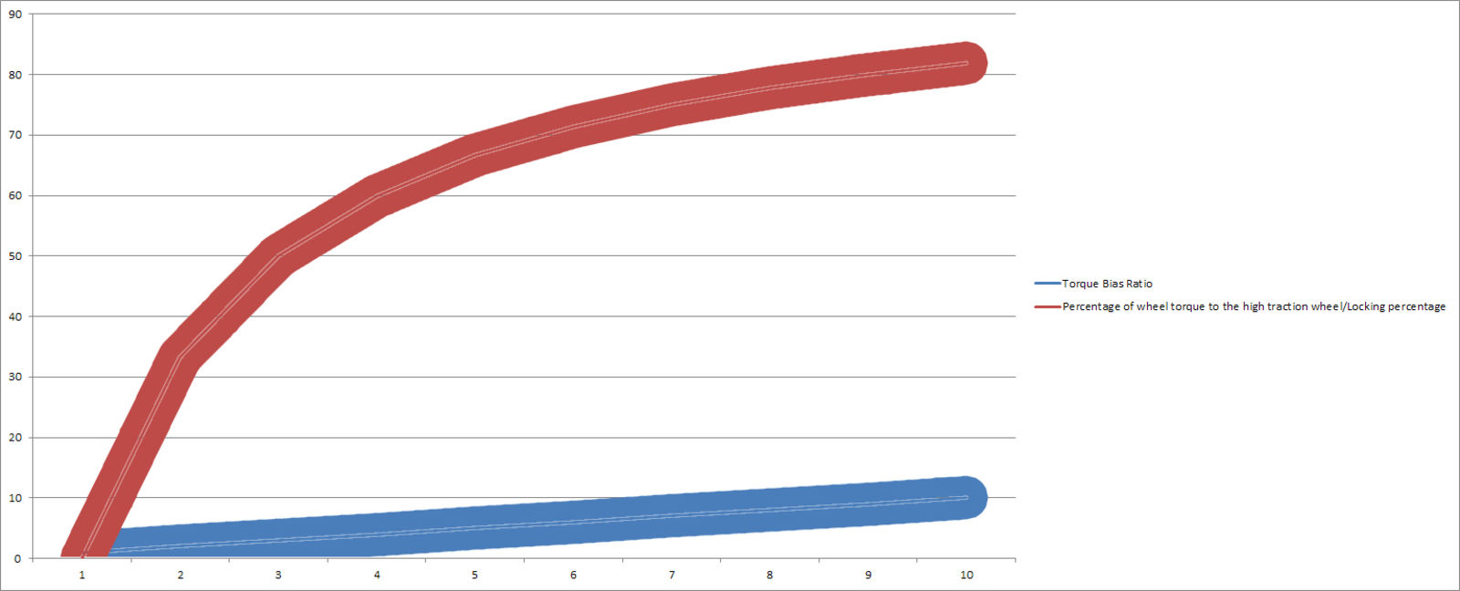
The graph above shows the relationship between torque bias ratio and the locking effect. As you can see you gain the greatest benefit at the start of the curve, with diminishing returns above a TBR of, say, 10. While this sounds like a disadvantage it’s actually a good thing because LSD’s typically rely on friction to generate a TBR and a higher TBR requires more friction which equates to more energy lost as heat. This also allows LSD’s to be very safe in high performance applications where shaft failure doesn’t allow a large torque bias that results in a dangerous yaw moment.
ELECTRONIC SYSTEMS
Electronic systems: Typically called electronic differentials, external differentials and traction control systems of various names, produce some of the results as an LSD but using different principles. TBR could be also called a “friction factor”, as it represents the level to which additional friction at the differential allows for a bias of forces across the axle. LSD’s use clutches, fluids, gear friction or other methods to generate this friction between the two shafts where locking diffs are essentially infinite friction.
The important distinction is where the friction is generated: If generated internally between the two shafts it allows for force to transfer from one side of the shaft to the other, if externally, there is no link between the shafts and no force can be sent across them.
What’s happening in this case then is NOT a torque bias, but rather cheating the math for the µ for each wheel. Note: For this example I am using the common setup of traction control with an open differential. Lets look at the number again
- 4000 lbs car
- 1000 lbs per wheel (assuming balanced car)
- µ snow = .3
- Tractive Force = 300 lbs (1000 x .3)
- 300 + 300 = 600
- (300 + 300) + 300 = 900 lbs
So yet again, only 600 lbs can be applied, but, what if you added friction to the slipping wheel to the tune of 300 lb-ft via the brake? Now there is effectively 600 lbs of force being applied to that wheel and because an open diff has a TBR of 1 that means 600 lbs is available to the high traction wheel, not just 300. The catch is that the brakes are taking up the slack torque of the low traction wheel so that max that side can still apply to the road is limited to 300 but 300 + 600 = 900 lbs which is sufficient to overcome inertia and you are on your way!
Systems that rely on open differentials are always limited in the amount of torque that they can apply by the Trg/2 to either wheel, which is just another way of expressing a TBR. What this means is that if the Trg is 1000 lbs-ft then the high traction wheel can only ever get 500 lbs-ft while the low traction wheel gets whatever it can apply + the friction of the brakes totaling up to 500 lbs-ft. This means the limiting factor to the traction equation is the Trg as opposed to the µ of the surface being the limiting factor with a TBR based system.
In the real world this is often more than sufficient to overcome inertia and accelerate but it’s not as effective as a high TBR in extreme situations and has several drawback, namely that the friction required is orders of magnitude higher than is required to create a TBR in the differential resulting in a lot of waster energy in addition to the fact that they are much slower to react, they affect speed bias much more significantly and its hard on the brakes and other system. Typically these systems are best used when a high Tgr can be achieved, either with brute force engines or additional reduction gearing like a transfer case with low range gearing.
These systems typically look like locked diffs in extreme situations (wheel in the air) but, in reality what you are really doing is tricking the open differential into normalizing the torque equation, not biasing torque. In situations where there is low Trg there may be insufficient torque to overcome inertia, just ask Carl…poor Carl.
Or this CR-V
BRAKE TORQUE BIASING
(start at 2:29 if it doesn’t jump)
Up to now we’ve made the assumption of an open diff with these systems, however these brake biasing systems can be combined with a traditional TBR LSD to great effect.
Take for example the HMMWV above with Torsen differentials front and rear with a TBR of 4.5:1. Apply the numbers
- 4000 lbs car
- 1000 lbs per wheel (assuming balanced car)
- µ snow = .3
- Tractive Force = 300 lbs (1000 x .3)
- x TBR 4.5:1 = 1350 lbs
- 1350 + 300 = 1650 total lbs force
Applying the TBR results in an already impressive bias of 1350 lbs to the high traction wheel which is plenty most of the time however as we discovered with traditional LSD’s this ratio is not infinite. When a tire is in the air there is still no torque being applied to the high traction wheel resulting in the “diagonal spin” known to most Subaru owners and demonstrated in the video. However, applying brake pressure to all wheels, allows the wheel in the air to get the required friction for a force to be applied, then you can apply the TBR and because the differential can bias a high ratio of torque the light application of brake pressure required to stop the wheel in the air from spinning is not close to enough to prevent the high traction wheel from overcoming it and applying the TBR of the differential to full effect minus the drag of the brake.
Example: 100 lbs of braking force applied on all wheels means that 450 lbs -100 lbs can go to the high traction wheel [(100*4.5)-100)] in this case, increasing the brake pressure increasing the effectiveness of the TBR. So 1000 lbs of braking force is 4500-1000 or 3500 lbs of force…plenty. Given that the Hummer can easily generate Trg numbers that high its as effective as a locking differential in practice without the disadvantage of losing speed bias and with having to overwork the brakes like a open diff setup.
If this seems like an ideal compromise remember that this is still limited to the Trg and that high bias LSD’s are expensive and provide marginal real world advantages over cheaper electronic solutions. The LSD with independent electronic brake biasing would be an idea solution for most use cases.
Well that’s pretty much it, hopefully you’ve learned something, I know I did writing it and I hope this helps you understand the pros and cons of these systems, why they are used and how to get the most out of them.