
UPDATE: I had my friend check in with a coworker with a PhD in EE take a look at it and while the relay method suggested by Shane Moore would work (thank you btw) the method provided by torque to yield (also, thank you) would work and with less wiring and fewer parts. So here’s how it’s going to look.
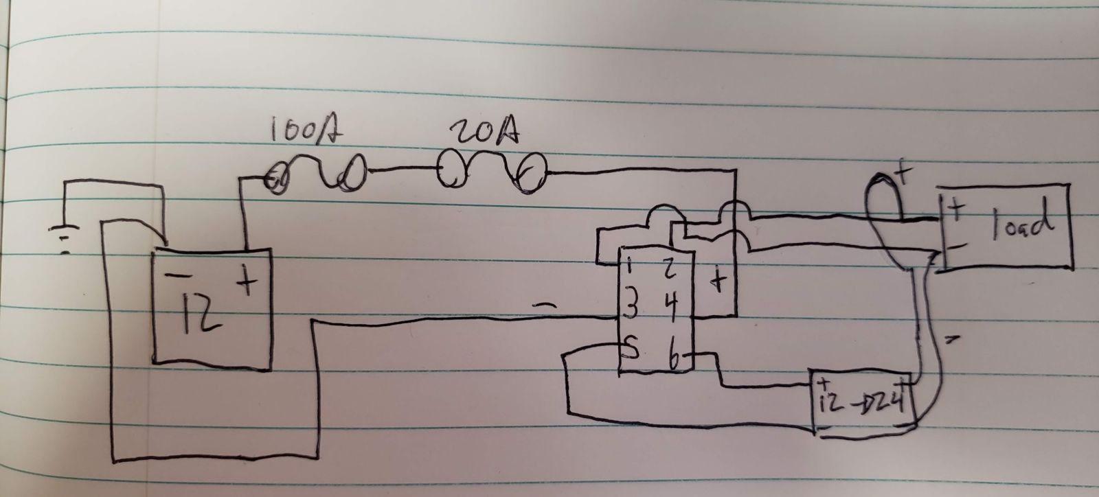
From the battery to a circuit breaker which goes to a fuse box, a 20 A fused + and a negative return on 14 AWG wire head out from the fuse box to a DPDT switch in the back. Pins 3/4 get the + and -, Pins 1/2 are 12v to load. Pins 5/6 are 12v to step-up converter then to load. The idea is that even though there is potential backfeed into the converter the broken current path at the switch prevents it (as was suggested by TTY). Im still a little nervous about this because I don’t know how the converter is wired. Is the circuit path broken inside the converter in such a way that a ground loop will form damaging it? I don’t know and the Chinese manufacture was...little help. Anyway, Im fairly confident. Thanks for your help!
I while back I ordered something from China (great idea I know). I want to be able to charge my Macbook without an inverter with DC current...since the adapter just converts AC to DC anyway I didn’t see the point of going through 2 inefficiency channels just to end up back at DC. Anyway, I discovered that while the adapter I bought CAN handle 60 watts at 20 volts required to charge the macbook it will not step up the voltage to meet that need. So I bought one of these
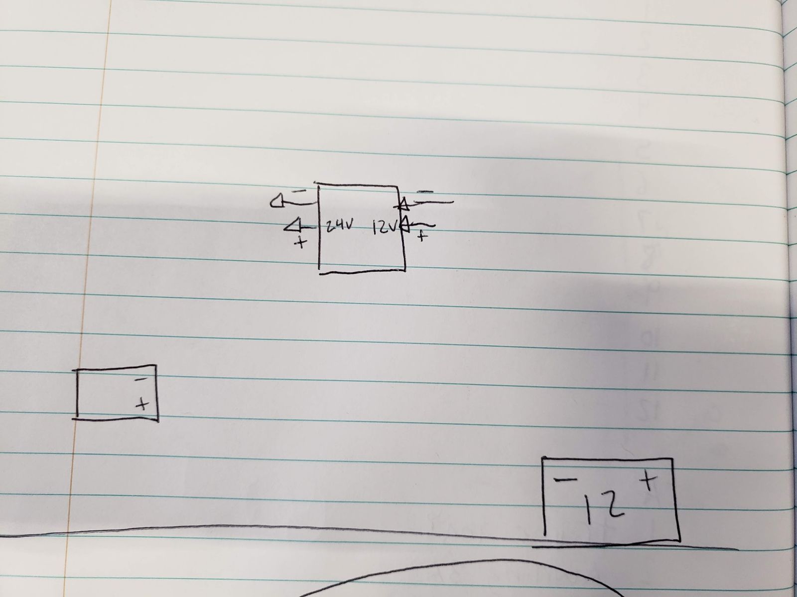
which will supply the required 24v that will then be stepped back down to 19.2V as required by the Macbook by the adapter. The thing is, this still has inefficiencies and at the loads I’m expecting I’m going to lose 10% to heat and and that’s lame if I want to, for example, charge my phone overnight on the trail. To go from 12V to 24V back down to 5W is wasteful so I want to be able to switch between 12v input to the adapter and 24V input. The trouble that I’m having is trying to find a suitable way to share input wires to the adapter seeing it will need to be, effectively, one set of wires to the adapter which means that It needs to share a ground, or I need to switch both the ground and supply both before and after the converter to bypass it completely (I don’t want the converter running unless I need the 24v).
Here is the basic diagram
Here is the one way I think I figured it out but I want to know if there is a better way
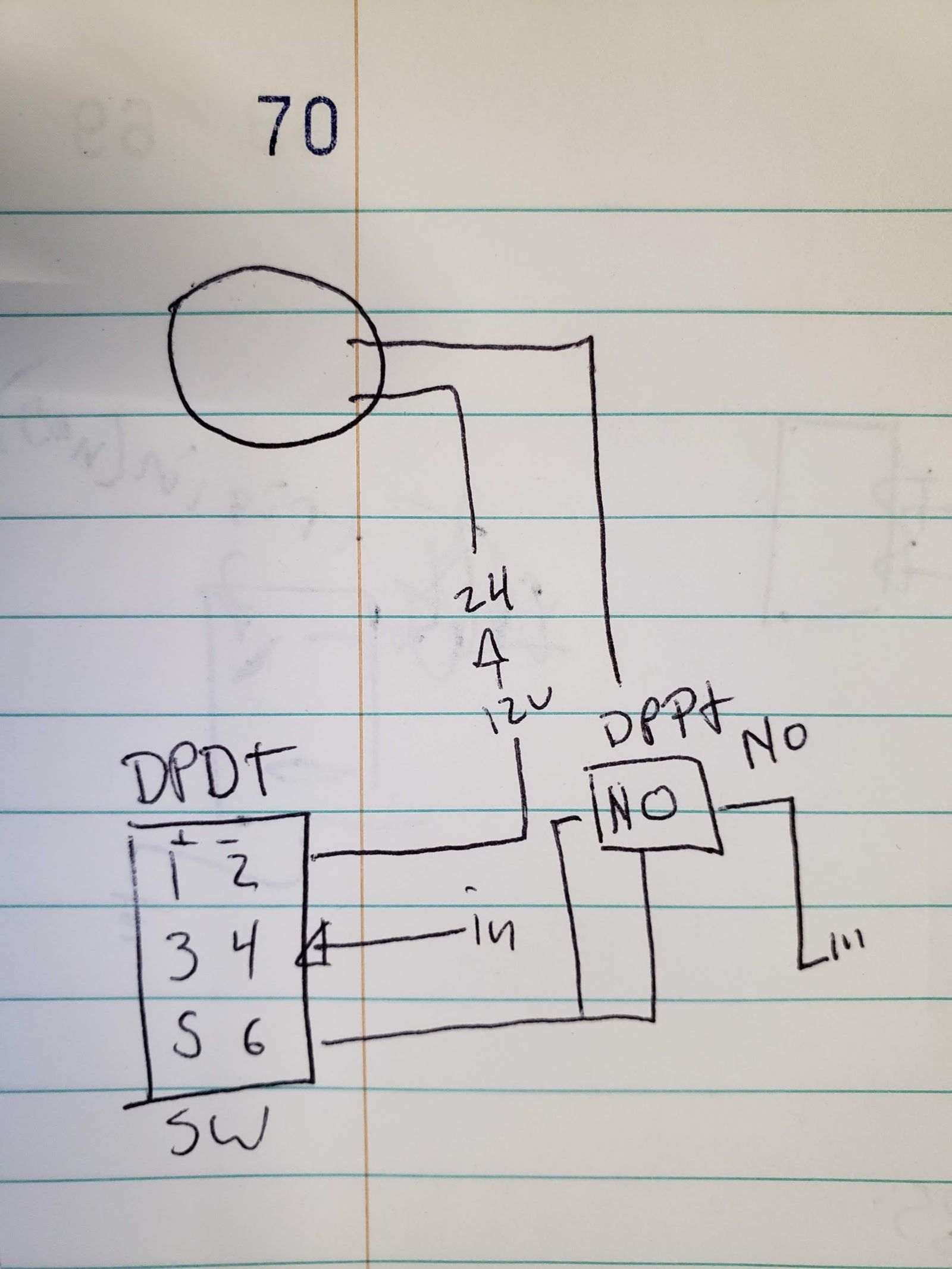
Both supply and ground would go to pins 3/4 of a DPDT switch. pins 1/2 would be the 12v supply and ground to the converter which then sends its supply and ground to the load. Pins 5/6 would go to a DPDT relay and supply the coil power so that when its switched the Normally Open contacts go closed and send supply on one pole and ground on the other pole to the load. That way when the switch is in the 1/2 position the backfeed hits a depowered relay in the normally open position. And in the 5/6 position the current doesn’t have a path and there is no backfeed. Though looking at it again in the morning reveals that there would be backfeed of 12v into the converter...which leads me back to where I started.
Without knowing how the boost converter works I don’t know what kinds of things happen with you try and backfeed a 24v output 12v in. If there is built in protection like diodes then I don’t need the relay or anything.
Basically I have to figure out a way to supply a load with both 12v normally and 24v optionally through a switch without having issues with 24V or 12v feedback on the shared lines going into the load.
Any thoughts? please?