In 1977, General Dynamics began work on the F-16 SCAMP (Supersonic Cruise And Maneuver Prototype), intended to be a quick project demonstrating the incorporation of SST technologies to military aircraft. The initial concept was to stretch the F-16's fuselage by 40" and changing the original clipped delta wing to a cranked-arrow delta wing. The new wing would be optimized for both low and high speed, and would increase the F-16's internal fuel carry capacity. GD worked with NASA Langley on constructing a windtunnel model, and the design was given the internal designation Model 400.
The initial Model 400 concept featured all moving wing tips, adapted from the horizontal tail surfaces from the F-16A, for roll control and an all moving vertical tail. These surfaces were later dropped as they did not provide adequate control at low speed, high angle of attack. Also, there would have been no provision for wing-tip mounted missiles. The main wing incorporated forebody strakes to enhance vortex generation for high angle of attack maneuverability, negative stability for improved subsonic lift and reduced supersonic drag. The Model 400 received backing from the USAF, and in 1980 the third (2-seat) and fifth (1-Seat) F-16 production airframes were returned to GD’s Fort Worth plant for modification.
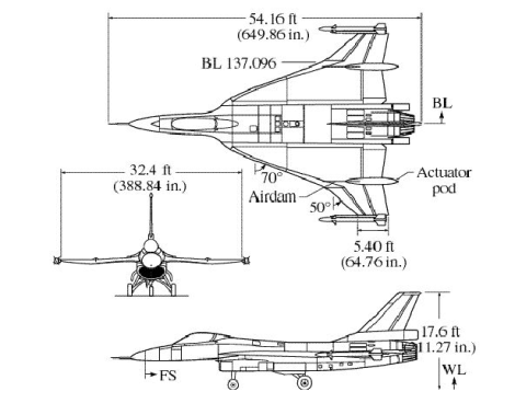
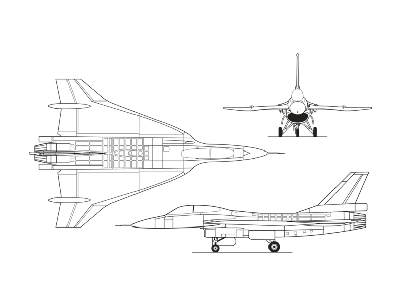
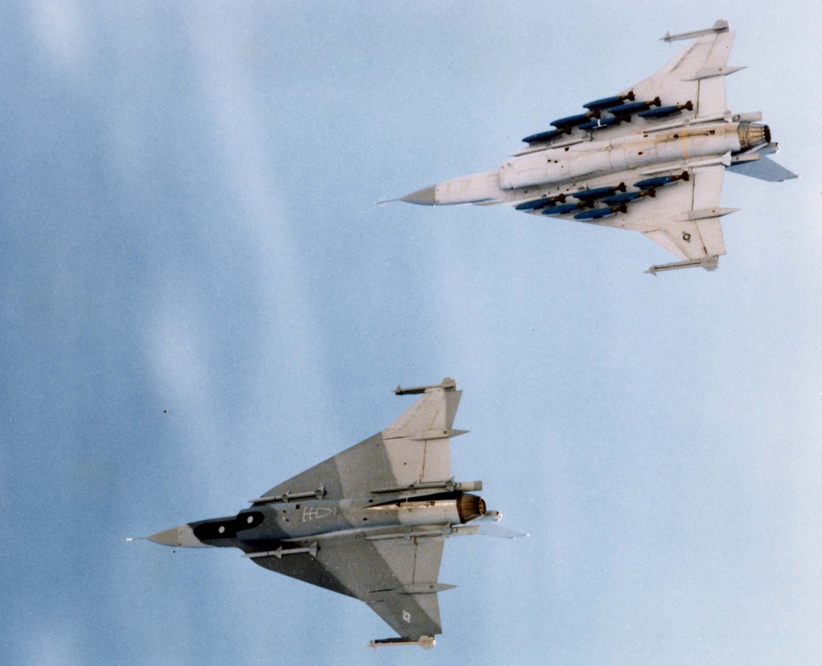
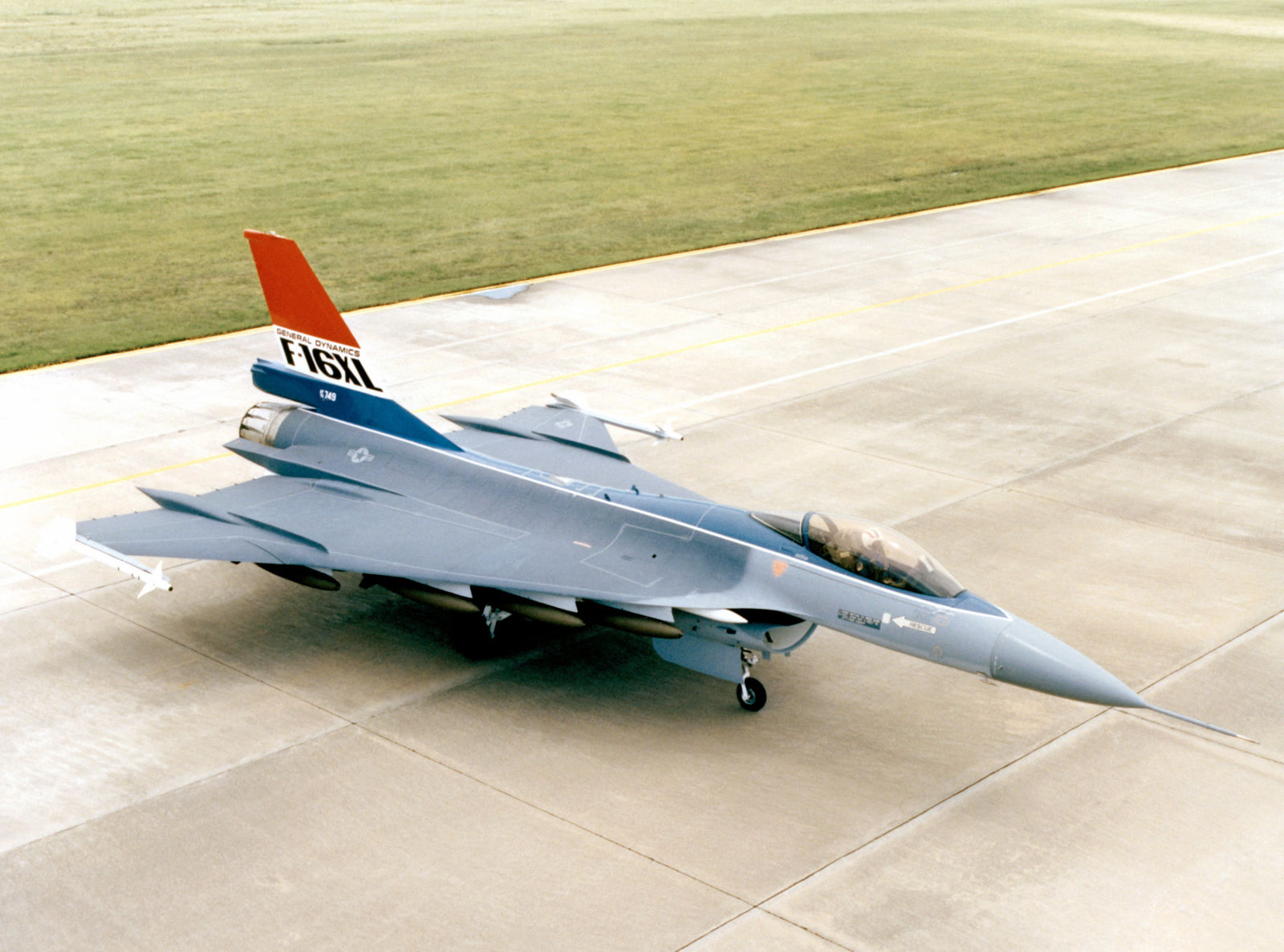
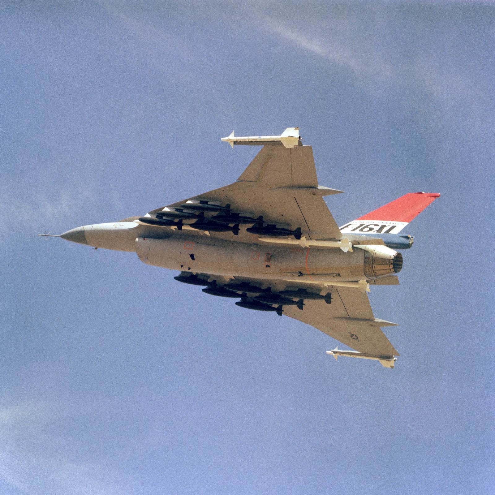
The cranked-arrow delta of the F-16XL was 120% larger than that of a standard F-16A, and increased fuel capacity by 82%. General Dynamics made extensive use of carbon fiber composites in building the F-16XLs, but the aircraft were still almost 3,000lbs heavier than an F-16A. The aircraft were 56" longer, with an additional two fuselage sections being added. The aerodynamic changes resulted in a 25% improvement in maximum lift-to-drag ratio in supersonic flight and 11% in subsonic flight, and a plane that reportedly handled much more smoothly at high speeds and low altitudes. The new wing provided a whopping 27 hardpoints for weapons and electronics pods:
- 16 wing stations of capacity 750 lb (340 kg) each
- 4 semi-recessed AIM-120 AMRAAM stations under fuselage
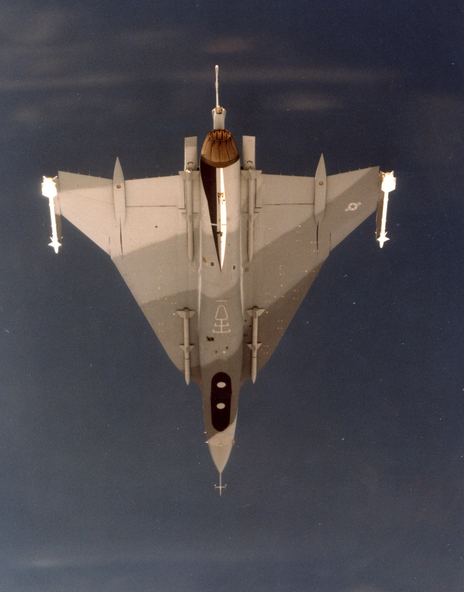
- 2 wingtip stations
- 1 centerline station
- 2 wing “heavy/wet” stations (these interfered with 4 adjacent stations, however)
- 2 chin LANTIRN stations
It was with these new capacities in mind that GD advanced the F-16XL as a contender in the USAF’s Enhanced Tactical Fighter program to procure a replacement for the F-111 Aardvark. The relative immaturity of the F-16XL, along with an Air Force preference for aircraft with two engines saw the F-15E win the ETF competition, and the two F-16XLs were placed into storage.
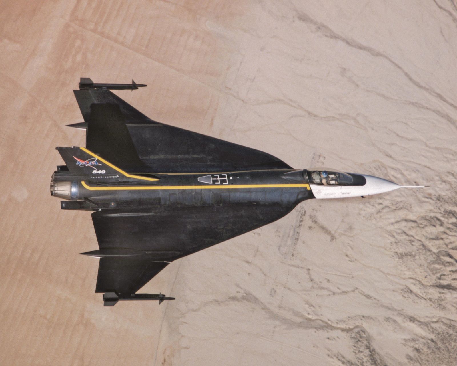
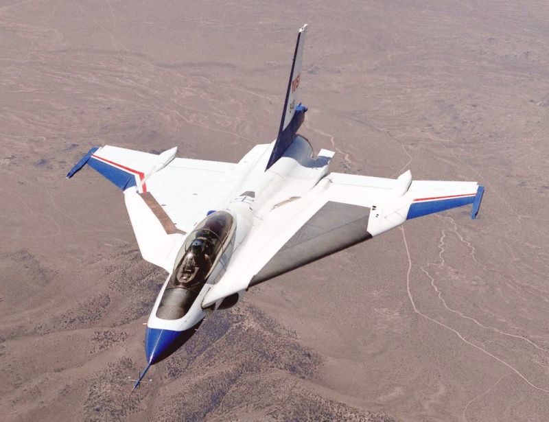
In 1988, both F-16XLs were taken out of storage and transferred to NASA’s Dryden FRC at Edwards AFB to act as research aircraft. The single seat model, F-16XL-1, was repainted in a smart paint scheme of black with gold piping and a white nose, was designated NASA #849, while F-16XL-2 was designated NASA #848 and was painted white with blue and red detailing. 849 was fitted with a titanium glove, designed and built by Rockwell International’s North American Aviation division, on the left wing. This glove had millions of holes, each 0.0025" in diameter, laser-drilled into it over an area of five square feet for the purpose of testing regarding active boundary layer control. Active suction would draw the disturbed layer of air from around the aircraft, restoring a laminar flow and reducing parasitic drag, which would (hopefully) result in reduced fuel usage and increase in speed and/or range.
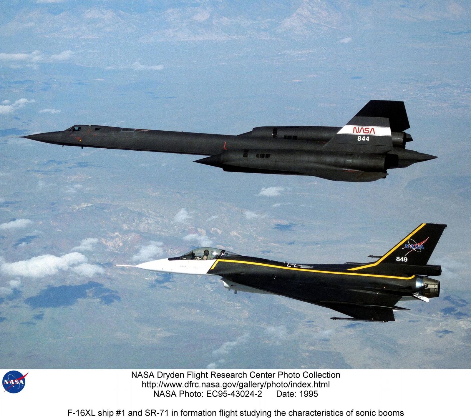
F-16XL-1 was later teamed with NASA’s SR-71A (#844) as part of a program to investigate sonic boom propagation. The SR-71 would fly at speeds from Mach 1.25 to Mach 1.6 at altitudes of 31,000 and 48,000 feet in steady, level flight, with the F-16 flying in formation and measured overpressures.
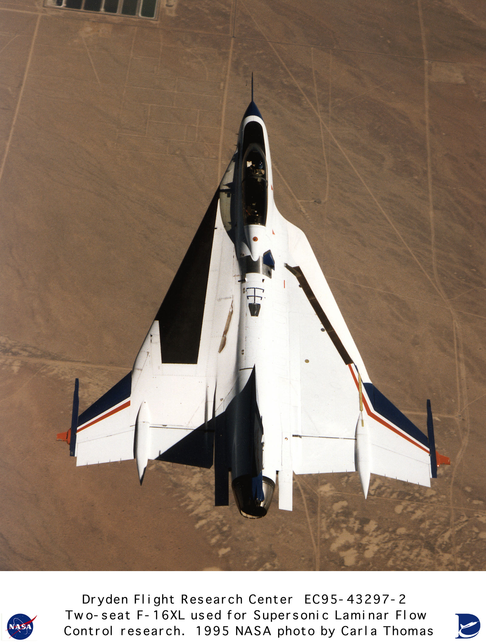
F-16XL-2, NASA #848, also investigated laminar flow at supersonic speeds, but it was fitted with two gloves, one on each wing. A passive glove (foam and fiberglass fairing) was installed on the right wing (the angled dark stripe in the above pic) in order to examine the aerodynamic fluid mechanics along the leading edge of a supersonic surface, noise environment, and pressure distribution.
On the left wing, a new active glove was installed (double the size of ship no. 1's glove) consisting of a foam and fiberglass fairing around a test section of a high-tech composite with a porous titanium skin. The glove has a maximum thickness of 2.5 inch, and covers 75% of the wing’s surface and 60% of its leading edge. It was designed by a NASA-contractor team which included the Langley Research Center, Dryden, Rockwell International, Boeing, and McDonnell Douglas. The wing’s S-Shaped blend was extended straight forward on the left side to match more closely the proposed wing for a proposed high speed civil transport. The active section, the middle 66% of the glove, has at least 2,500 laser-drilled holes and has an approximate area of 10 sq feet. The holes lead into 20 cavities beneath the wing’s surface, which are used to control the suction at the wing’s surface. The glove is chemically bonded to the skin itself with common epoxy resins. After the paint is removed from the aircraft, a couple of fiberglass layers are applied onto the skin of composite material, serving as protection for the skin when the glove is taken off again.
Both F-16Xls were retired again after the conclusion of their test programs, and were turned over to the Air Force Test Flight Museum for storage. The single seat article, SN 75-0747, is on display, while SN-75-0749 is currently in storage.